$14
VOLVO L110E WHEEL LOADER SERVICE REPAIR MANUAL PDF – 1617 PAGES
Technical Service and Workshop Repair Documentation for the Volvo L110E
The Volvo L110E Wheel Loader Service Repair Manual provides an extensive collection of technical information for understanding, inspecting, troubleshooting, maintaining, and repairing the Volvo L110E wheel loader.
Containing 1,617 pages with information updated in 2021, this digital PDF workshop publication covers the engine, electronic fuel injection, electrical controls, power transmission, torque converter, drive axles, braking equipment, steering, cab systems, and working hydraulics.
Its contents combine system descriptions with practical repair procedures, pressure testing instructions, electrical wiring diagrams, hydraulic circuit diagrams, equipment installation information, workshop safety precautions, and technical specifications.
Particular attention is given to the D7 engine, electronic fuel delivery, APS II transmission control, VCADS Pro diagnostics, Comfort Drive Control (CDC), Boom Suspension System (BSS), and automatic Return-to-Dig function.
The manual also includes procedures for checking hydraulic pump pressures, servicing the braking system, adjusting steering components, replacing engine parts, and diagnosing electrical control functions.
Whether the task involves investigating a transmission fault, inspecting fuel injection components, or checking the hydraulic system, this publication provides a structured technical reference for workshop operations.
MANUAL DETAILS
- Manufacturer: Volvo Construction Equipment
- Machine Model: Volvo L110E Wheel Loader
- Manual Category: Service Repair / Workshop Manual
- File Format: PDF
- Number of Pages: 1,617
- Information Updated: 2021
- Delivery: Digital Download
COMPLETE OVERVIEW OF MANUAL CONTENTS
The documentation is divided into technical descriptions, electrical and hydraulic diagrams, installation instructions, repair procedures, safety information, and specifications.
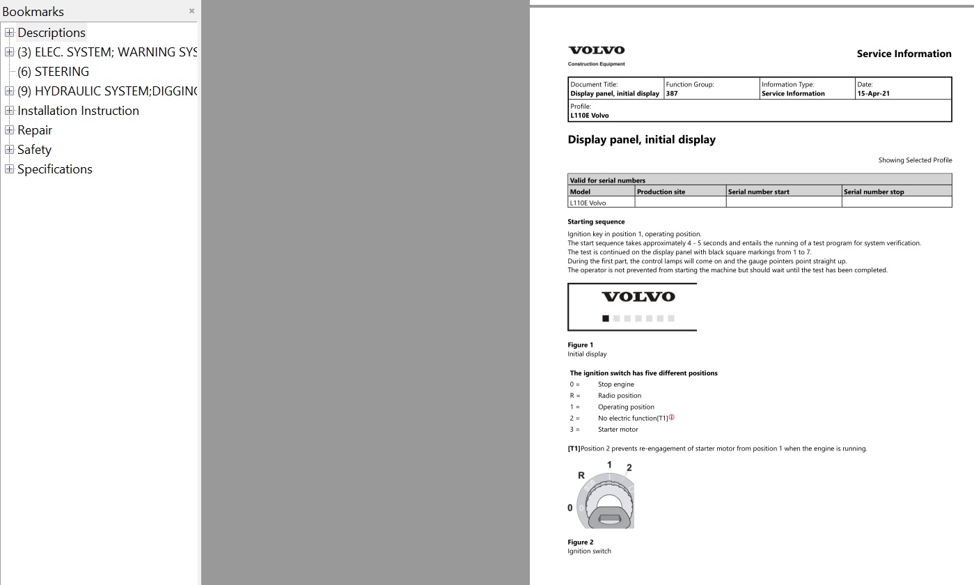
1. GENERAL SERVICE AND MAINTENANCE INFORMATION
The general section provides introductory information and service procedures used when maintaining the machine.
Included topics:
- General technical descriptions
- Battery charging
- Cleanliness requirements for hydraulic and brake systems
- Electric welding precautions
- Hydraulic system repair instructions
- Electrical system service precautions
- Manual parking brake release
- Recommended lubricants and oils
2. D7 ENGINE – CONSTRUCTION AND OPERATION
The engine section contains detailed information about the engine's mechanical construction and operating systems.
ENGINE MECHANICAL COMPONENTS
- D7 cylinder block
- Crankcase ventilation
- Cylinder head
- Cylinder head gasket
- Cylinder liners
- Crankshaft
- Connecting rods
- Pistons
- Camshaft
- Engine timing gears
- Valve mechanism
- Engine vibration damper
- Engine mountings
ENGINE SUPPORTING SYSTEMS
- Engine lubrication system
- Engine oil pump
- Engine cooling system
- Engine air cleaner
- Engine turbocharger
- Engine preheating coil
- Engine control unit
- Internal Exhaust Gas Recirculation (IEGR)
3. ELECTRONIC FUEL INJECTION SYSTEM
The manual contains descriptions and service information for the engine fuel injection equipment.
FUEL SYSTEM COMPONENTS
- Fuel feed pump
- Fuel filters
- High-pressure fuel pump
- Fuel rail
- Fuel injectors
- Fuel Control Valve (FCV)
- Pressure Relief Valve (PRV)
- Fuel rail pressure sensor
- Unit pump descriptions
FUEL SYSTEM SERVICE PROCEDURES
- Fuel system bleeding
- Fuel feed pressure testing
- Fuel Control Valve inspection
- Fuel Control Valve replacement
- High-pressure fuel pump inspection
- High-pressure fuel pump replacement
- Fuel rail pressure sensor replacement
- Fuel injector replacement
- Pressure Relief Valve inspection
- Pressure Relief Valve replacement
The documentation also includes instructions and precautions for working with electronically controlled fuel injection.
4. ENGINE COOLING AND REVERSIBLE FAN SYSTEM
The Volvo L110E manual includes technical information for the cooling equipment and its hydraulic controls.
COOLING SYSTEM
- Cooling system descriptions
- Cooling fan speed control
- Cooling fan motor
- Reversible cooling fan
- Electric reversible fan controls
- Reversible fan hydraulic diagram
- Reversible fan fault indication and troubleshooting
COOLING SYSTEM REPAIRS
- Coolant pump replacement
- Cooling fan hydraulic function testing
- Cooling fan motor replacement
- Radiator removal and installation
- Thermostat replacement
- Reversible cooling fan function testing
- Cooling fan maximum speed checks
- Hydraulic pump P3 fan pressure testing
5. ENGINE REPAIR AND INSPECTION PROCEDURES
The repair section contains procedures for major engine maintenance and component replacement.
ENGINE MECHANICAL REPAIRS
- Engine removal
- Engine installation
- Front engine mounting replacement
- Front crankshaft oil seal replacement
- Engine cylinder compression testing
- Engine oil pan resealing
- Engine oil pressure testing
- Valve clearance adjustment
- Engine stall speed testing
- Turbocharger inspection
ADDITIONAL ENGINE OPERATIONS
- Engine ECU removal
- Cooling system service
- Fuel system bleeding
- Fuel pump unit replacement
- Engine fan hydraulic testing
- Fuel injection component replacement
6. ELECTRICAL SYSTEM AND ELECTRONIC CONTROL
The electrical section provides descriptions of the machine's electrical circuits, monitoring functions, and electronic control systems.
ELECTRICAL COMPONENTS
- Alternator
- Battery
- Starter motor
- Electrical distribution box
- Sensors and switches
- Relays and fuses
- Solenoid valves
- Electrical control and warning lights
- Electrical wiring and connectors
- Electrical grounding points
ELECTRONIC CONTROL UNITS
- Engine Control Unit (E-ECU)
- Instrument Control Unit (I-ECU)
- Vehicle Control Unit (V-ECU)
ELECTRONIC CONTROL FUNCTIONS
- Electronic system descriptions
- Communication with data buses
- Software parameters
- ECU voltage supply
- Sensor voltage supply
- Computer communication faults
- SAE error codes
- Diagnostic strategies
7. INSTRUMENT PANEL AND MACHINE MONITORING
The manual contains detailed information for monitoring engine, transmission, hydraulic, and electrical operating conditions.
ENGINE MONITORING
- Engine speed
- Engine oil pressure
- Engine oil level
- Engine coolant temperature
- Engine protection
- Engine shutdown
- Fuel level
- Fuel temperature
- Boost pressure
- Air intake temperature
- Engine preheating
TRANSMISSION MONITORING
- Transmission oil pressure
- Transmission oil temperature
- Transmission oil level
- Transmission filter monitoring
- Transmission slipping
- Transmission overspeed
- Gear selection
- Transmission protection
OTHER MONITORED FUNCTIONS
- Brake pressure
- Brake pressure charging
- Parking brake
- Differential lock
- Hydraulic oil level
- Hydraulic oil temperature
- Central lubrication
- Boom Suspension System
- Attachment locking
- Secondary steering
- Travel speed
- Service intervals
8. VCADS PRO DIAGNOSTICS
The manual includes references to VCADS Pro service equipment and diagnostic operations.
Included topics:
- VCADS Pro service tool
- General fault diagnosis
- Special troubleshooting tools
- Electrical connector inspection
- SAE error code interpretation
- Software parameter settings
- Service display information
- Engine and transmission diagnostic references
9. ELECTRICAL WIRING DIAGRAMS
The documentation includes numbered wiring diagrams covering the machine's electrical systems.
WIRING DIAGRAM COLLECTION
- Wiring diagrams 1–13
- Wiring diagram 15B
- Wiring diagrams 16–35
- Wiring diagrams 101, 102, 103 and 107
- Additional diagram versions 9B, 19C, 21B and 21C
- Updated CDC wiring diagram 17
- Heavy-duty 120 A alternator information
These diagrams support electrical circuit identification, component tracing, and troubleshooting.
10. APS II AND HYDRAULIC TRANSMISSION
The power transmission section includes information about automatic transmission functions and major driveline components.
TRANSMISSION OPERATION
- APS II Automatic Power Shift
- Gear selector functions
- Gear shifting solenoids
- Gear selector valve
- Hydraulic transmission operation
- Transmission protection
- Transmission disengagement
- Torque converter
- Planetary gears
- Final drive
TRANSMISSION REPAIR
- Transmission removal
- Transmission installation
- Transmission oil pressure testing
- Gear selector valve removal and installation
- Gear selector solenoid resistance measurement
- Torque converter removal and installation
11. DRIVE AXLES AND DIFFERENTIALS
The manual contains repair procedures for the front and rear axles.
Included topics:
- Front axle removal and installation
- Rear axle removal and installation
- Differential lock operation
- Differential lock sensor adjustment
- Drive shaft replacement
- Hub seal replacement
- Rear axle mounting axial and radial play measurement
- Final drive descriptions
12. BRAKE SYSTEM SERVICE
The brake section includes procedures for inspecting brake components and evaluating hydraulic braking performance.
BRAKE SYSTEM COMPONENTS
- Foot brake valve
- Parking brake
- Brake wear indicators
- Brake accumulators
BRAKE SERVICE PROCEDURES
- Brake accumulator inspection
- Brake disc replacement
- Brake disc wear measurement
- Brake hydraulic function testing
- Brake system bleeding
- Brake retardation testing
- Foot brake pedal adjustment
- Foot brake valve reconditioning
- Parking brake mechanical release
- Brake circuit pressure testing and adjustment
13. STEERING SYSTEM AND COMFORT DRIVE CONTROL
The steering section includes hydraulic steering information and service procedures for the CDC lever steering system.
STEERING COMPONENTS
- Steering valve
- Steering cylinders
- Hydraulic steering pump
- Steering shift valve
- Secondary steering
- Steering control valve
COMFORT DRIVE CONTROL (CDC)
- CDC system description
- CDC electrical system
- CDC hydraulic system
- Lever steering signals
- Lever steering speed adjustment
- CDC control valve adjustment
STEERING SERVICE
- Steering valve replacement
- Steering valve reconditioning
- Steering cylinder replacement
- Steering hydraulic pressure testing
- Load-sensing pressure testing for pumps P1 and P2
- Secondary steering function testing
14. FRAME, CAB AND CLIMATE CONTROL
The manual also provides information for structural and operator environment components.
FRAME
- Frame descriptions
- Counterweight replacement
- Wheel removal and installation
CAB AND CLIMATE EQUIPMENT
- Cab description
- Cab suspension
- Air conditioning system
- Automatic Temperature Control (ATC)
- Software-controlled air conditioning
- Cab removal and installation
- Engine hood removal and installation
- Evaporator cleaning
- Heater core replacement
- Fan motor replacement
- Heat control valve replacement
- Viscous cab suspension replacement
15. WORKING HYDRAULIC SYSTEM
The hydraulic section explains the operation of the machine's working equipment and hydraulic control circuits.
HYDRAULIC COMPONENTS
- Hydraulic oil tank
- Hydraulic pumps
- Central hydraulic block
- Hydraulic control valve
- Servo system
- Hydraulic pressure monitoring
- Lift cylinders
- Tilt cylinders
- Hydraulic attachment locking
HYDRAULIC PUMP SERVICE
- Hydraulic pump maximum working pressure testing
- Hydraulic standby pressure testing
- Hydraulic pump P1 load-sensing pressure checks
- Hydraulic pump P2 load-sensing pressure checks
- Hydraulic pump P1 and P2 flow control
- Hydraulic pump P3 fan and brake circuit checks
- Hydraulic pressure adjustment
16. BOOM SUSPENSION SYSTEM (BSS)
The manual includes descriptions and service procedures for the Boom Suspension System.
Included topics:
- BSS operating description
- BSS hydraulic components
- Boom suspension accumulator replacement
- Hydraulic accumulator depressurization
- Accumulator reconditioning
- Precharge pressure testing and adjustment
- BSS pressure-reducing valve adjustment
- Boom Suspension System troubleshooting
- Test drive with load
17. RETURN-TO-DIG AND HYDRAULIC ATTACHMENT CONTROL
The documentation includes information for automatic lifting arm control and attachment locking.
RETURN-TO-DIG
- Automatic lift arm lowering
- Return-to-Dig operation
- Return-to-Dig valve block
- Return-to-Dig installation instructions
ATTACHMENT EQUIPMENT
- Hydraulic attachment locking
- Software-controlled attachment lock
- Hydraulic attachment lock with raised servo pressure
- Attachment bracket cylinder reconditioning
- Hydraulic attachment locking cylinder replacement
- Implement attachment hydraulic cylinder replacement
18. THIRD AND FOURTH HYDRAULIC FUNCTIONS
The manual includes descriptions and adjustment information for auxiliary hydraulic functions.
Included topics:
- Third hydraulic function
- Fourth hydraulic function
- Auxiliary hydraulic circuit descriptions
- Maximum hydraulic pressure testing
- Hydraulic pressure adjustment
- Auxiliary function installation instructions
19. CENTRAL LUBRICATION SYSTEM
The manual contains information about automatic lubrication equipment.
Included topics:
- Central lubrication system description
- Lubrication cycle
- Lubrication cycle selection
- Lubrication system specifications
- Lubrication system operating functions
20. HYDRAULIC SYSTEM DIAGRAMS
The documentation contains hydraulic diagrams for several machine configurations.
Included diagrams:
- Complete hydraulic diagram
- Hydraulic diagram for fan and brake system
- Hydraulic diagram for reversible fan and brake system
- Steering hydraulic diagram
- Steering diagram with CDC and secondary steering
- Working hydraulics and differential lock diagram
- Working hydraulics with differential lock and BSS
- Working hydraulics with differential lock, BSS, attachment locking, and third/fourth functions
These diagrams are useful for understanding hydraulic circuit operation and component connections.
21. OPTIONAL EQUIPMENT INSTALLATION INSTRUCTIONS
The manual includes installation instructions for selected additional equipment.
Included equipment:
- Third hydraulic function
- Fourth hydraulic function
- Hydraulic attachment locking
- CareTrack
- 120V engine heater
- Additional working lights
- Front working lights
- Heat insulation kit
- Lever steering
- Wide operator seat mounting kit
- Oil-bath air cleaner
- Radio installation kit
- Return-to-Dig equipment
- Reversible cooling fan
- Single-lever hydraulic control
- Tail lamp guard
22. WORKSHOP SAFETY PROCEDURES
The safety section contains precautions for working with heavy machinery and potentially hazardous systems.
Included topics:
- General workshop safety
- Safe machine handling
- Safe lifting and supporting
- Hydraulic accumulator safety
- Hydraulic system precautions
- Battery safety
- Fuel and oil handling
- Air conditioning refrigerant safety
- Tyre handling
- Fire prevention
- Fire and heat exposure checks
- Environmental protection
- Waste handling
- Working under a raised boom
23. TECHNICAL SPECIFICATIONS
The specifications section provides reference data for major machine systems.
ENGINE SPECIFICATIONS
- Engine specifications
- Engine capacities
- Fuel system specifications
- Fuel feed pump specifications
- Injector specifications
- Injection pump specifications
- Cooling system specifications
- Intercooler specifications
- Lubrication system specifications
- Engine tightening torques
ELECTRICAL SPECIFICATIONS
- Alternator specifications
- Battery specifications
- Starter motor specifications
- Electrical system specifications
- Lighting specifications
POWER TRANSMISSION
- Hydraulic transmission specifications
- Torque converter specifications
- Transmission fluid volume
- Front axle specifications
- Rear axle specifications
- Axle capacities
- Driveline tightening torques
BRAKE AND STEERING
- Brake accumulator specifications
- Brake valve specifications
- Parking brake specifications
- Front and rear wheel brake specifications
- Steering system specifications
- Steering hydraulic tightening torques
HYDRAULIC EQUIPMENT
- Hydraulic pump P1 specifications
- Hydraulic pump P2 specifications
- Hydraulic pump P3 specifications
- Hydraulic system volume
- Servo system specifications
- Boom Suspension System specifications
- Boom and cylinder specifications
- Central lubrication system specifications
ADDITIONAL TECHNICAL DATA
- Air conditioning specifications
- Refrigerant quantities
- Machine component weights
- Wheel specifications
- Frame specifications
- Tightening torques
- Conversion tables
- Alternative fuels
WHY THIS MANUAL IS USEFUL
The Volvo L110E combines a mechanically complex powertrain with electronically controlled engine, transmission, and hydraulic functions.
This workshop publication helps bring those systems into a single technical reference.
It can support:
- Engine mechanical inspection
- Electronic fuel injection servicing
- Cooling system and fan repairs
- Electrical fault investigation
- VCADS Pro diagnostic work
- APS II transmission servicing
- Torque converter and axle repairs
- Brake hydraulic pressure testing
- CDC steering adjustments
- Hydraulic pump pressure checks
- Boom Suspension System repairs
- Return-to-Dig system servicing
- Auxiliary hydraulic function maintenance
- Technical specification verification
WHO IS THIS MANUAL FOR?
This publication is suitable for:
- Volvo construction equipment service technicians
- Professional heavy equipment mechanics
- Independent machinery repair workshops
- Fleet maintenance departments
- Construction equipment maintenance companies
- Experienced Volvo L110E owners responsible for repairs
IMPORTANT COMPATIBILITY INFORMATION
This manual is identified for the Volvo L110E Wheel Loader.
The documentation includes different hydraulic configurations, electrical diagram versions, and optional equipment.
Before purchasing, verify the machine model, serial number, and installed equipment to ensure that the relevant procedures match your machine.
The 2021 information update refers to the supplied documentation and does not necessarily indicate the machine's manufacturing year.
DIGITAL PDF DOWNLOAD
This product is supplied as a digital PDF workshop manual.
Included documentation:
- 1,617 pages of technical information
- D7 engine descriptions and repair procedures
- Electronic fuel injection system documentation
- Engine cooling and reversible fan information
- Electrical control system descriptions
- VCADS Pro diagnostic references
- Electrical wiring diagrams
- APS II transmission and torque converter information
- Front and rear axle repair procedures
- Brake and steering service instructions
- Comfort Drive Control documentation
- Working hydraulic system repairs
- Boom Suspension System information
- Return-to-Dig system descriptions
- Hydraulic circuit diagrams
- Optional equipment installation instructions
- Workshop safety procedures
- Technical specifications and tightening torque references
Digital product only – no physical book will be shipped.
A compatible PDF reader is required to view the manual.
RELATED VOLVO MANUALS
Looking for technical documentation for other Volvo wheel loaders?
BROWSE VOLVO WHEEL LOADER MANUALS
Explore additional service repair manuals and parts catalogs for Volvo wheel loaders.
VIEW ALL VOLVO EQUIPMENT MANUALS
Find technical publications for other Volvo construction equipment models.
EXPLORE THE COMPLETE MANUAL COLLECTION
Browse service repair manuals and parts catalogs for construction and industrial equipment.
Always verify equipment compatibility before purchasing.
Detailed contents:
Descriptions
(0) GENERAL
Description
(1) STANDARD PARTS, SERVICE
Charging batteries
Cleanliness, brake and hydraulic systems
Electric welding
Parking brake, manually releasing
Recommended lubricants, oils
Repairing hydraulic system
Working on the electrical system of the machine
(2) ENGINE WITH MOUNTING AND EQUIPMENT
Air cleaner, description
Camshaft, description 2
Camshaft, description
Connecting rod, description
Control unit, description 2
Control unit, description
Cooling system, description 2
Cooling system, description
Crankshaft, description
Cylinder head gasket, description
Cylinder head, description
Cylinder liner, description
D7 cylinder block with crankcase ventilation, description and operation
Engine mounting, description
Engine timing gear, description
Engine, description 2
Engine, description
Fan speed control, description
Fuel feed pump, description
Fuel filter, description
Fuel rail, description
Fuel system, description 2
Fuel system, description
High pressure fuel pump, description
Injectors, description 2
Injectors, description
Instructions for working with electronic fuel injection
Internal Exhaust Gas Recirculation (IEGR), description
Lubrication system, description
Oil pump, description
Pistons, description
Preheating coil, description
Reversible cooling fan 2
Reversible cooling fan, electric description
Reversible cooling fan, hydraulic diagram description
Reversible cooling fan, trouble-shooting fault indication.
Reversible cooling fan
Turbocharger, description
Unit pump, description
Valves, description
Vibration damper, description 2
Vibration damper, description
(3) ELEC. SYSTEM; WARNING SYSTEM; INFORMATION SYSTEM; INSTRUMENTS
Abbreviations, wiring diagrams
Accelerator Pedal
Air filter pressure
Alternator, description
APS II
APS
Attachment locking
Automatic engine shut-off
Automatic lift arm lowering (Return to dig)
Axle oil temperature
Back-up alarm
Barometric pressure
Battery, changing
Battery, charging
Battery, description
Boom Suspension System (BSS) 2
Boom Suspension System (BSS)
Boost pressure
Brake pressure charging
Brake pressure
Brake test
Cable and component designations
Cable and component marking explanations 2
Cable and component marking explanations
Camshaft speed
Central lubrication, status indication
Central lubrication
Charge-air temperature 2
Charge-air temperature
Collection of basic data
Communication cable explanation
Communication with data buses 2
Communication with data buses
Component list 1 alternator, batteries, capacitors, electronic units
Component list 2 diodes
Component list 3 fuses
Component list 4 heating coils, instruments, service connections
Component list 5 lights
Component list 6 control-, warning lights
Component list 7 solenoid valves
Component list 9 relays
Component list 10 Signals, shift solenoids
Component list 11 sensors
Component list 12 switches
Component list Motors, resistors, monitoring system
Conditions when checking
Connecting special tools
Connectors, overview
Coolant Level
Coolant temperature, engine 2
Coolant temperature, engine
Coolant temperature, outlet radiator
Cooling fan adjustment
Description of table for software functions
Differential lock
Display panel and keypad, general
Display panel, information displays
Display panel, initial display
Display panel, operating display
Downshifting signal
Electrical distribution box, description
Electrical symbols and designations
Electrical system, description
Electrical system, work instructions
Electronic control system, description
Engine control unit E-ECU, description
Engine Oil Level
Engine oil pressure 2
Engine oil pressure
Engine On Off
Engine Protection
Engine Shutdown
Engine speed for E-ECU 2
Engine speed for E-ECU
Engine speed for V-ECU
Exhaust Gas Recirculation (EGR)
Frame ground connections and signal ground
Fuel consumption
Fuel Level 2
Fuel Level
Fuel temperature
Fully automatic
Gear Selector
Gearshifting solenoids
General fault diagnosis information
Hand Throttle
Hydraulic Oil Level
Hydraulic oil temperature
Hydraulic power limitation
Increased engine rpm
Increased fan speed for AC
Indication of serious engine fault
Information display unit, setting 2
Information display unit, setting
Information display, general
Injectors
Instrument control unit I-ECU, functional description
Instruments
Interruption in computer communication
Interval Wiper
Key feed
Lead and connector checks
Lighting, description
Middle instrument panel with warning light
Outdoor temperature
Output brake pressure
Overspeed, transmission
Parking brake
Preheating coil, description 2
Preheating coil, description
Preheating of inlet air
Preheating, description
Protection for high fuel temperature, common rail
Reduced computer communication
SAE error codes, translation to error messages, general
Secondary steering
Service display unit, axles and brakes
Service display unit, electrical control input signals 1
Service display unit, electrical control input signals 2
Service display unit, electrical control input signals 3
Service display unit, electrical control output signals 1
Service display unit, electrical control output signals 2
Service display unit, electrical system battery voltage
Service display unit, engine
Service display unit, general
Service display unit, hydraulics
Service display unit, settings
Service display unit, transmission
Service interval
Service panel, electrical feed sensor
Setting software parameters
Soft start and safety for AC
Software functions per function group
Software, description
Special tools for troubleshooting
Speed limitation for lever steering (CDC)
Speed limitation
Starter motor engagement
Starting system, description
System voltage
Temperature induction air
Theft protection
Time-controlled high idle
Tire radius
Transmission disengagement
Transmission oil filter
Transmission oil level
Transmission oil pressure
Transmission oil temperature 2
Transmission oil temperature
Transmission protection
Transmission slipping 2
Transmission slipping
Travelling speed
Troubleshooting strategy
Troubleshooting tools
Turbine speed
Unit pumps
VCADS Pro service tool
Vehicle control unit V-ECU, description
Voltage feed E-ECU, I-ECU, V-ECU
Voltage feed for sensors
Warming of hydraulic oil
Washer fluid level
Water in fuel
Wiping during and after washing
(4) POWER TRANSMISSION
Description 2
Description
Differential lock
Drive shaft, changing 2
Drive shaft, changing
Final drive
Gear selector valve, measuring resistance of solenoids
Gearshifting, description
General description
Hydraulic transmission, description
Planetary gear
Transmission, installing
Transmission, removing
(5) BRAKE
Foot brake valve, description
General description
Parking brake, description
Wear indicator, description
(6) STEERING
Comfort Drive Control, description
Control valve, description
Electrical system, description
Hydraulic pump, description
Hydraulic system, description
Secondary steering, description
Shift valve, description
Shift valve, function description
Steering cylinder, sectional view
Steering valve, description
Steering, description
Steering, function descriptioN
(7) FRAME; SPRINGS; DAMPING; AXLE SUSPENSION; WHEEL, TRACK UNIT
Counterweight, replacing
Frame, description
(8) MACHINERY HOUSE; CAB; EXTERIOR TRIM PARTS ANYWHERE
AC software-controlled, description
Air conditioning, description
ATC, description
Cab suspension, description
Cab, description
Climate control system, description
Components
(9) HYDRAULIC SYSTEM, DIGGING, HANDLING, GRADING EQUIPM, MISC. EQUIP
3rd, alternatively 3rd 4th hydraulic function, description
Automatic lift arm lowering (Return-To-Dig), description
Boom Suspension System, description of function
Boom Suspension System, description
Boom, description
Central block, description
Central lubrication system, description
Control valve, description
Hydraulic attachment lock (software-controlled), description
Hydraulic attachment lock with raised servo pressure, description
Hydraulic couplings, description
Hydraulic oil tank, description
Hydraulic pump, description
Hydraulic pumps, description
Hydraulic system, description
Lifting cylinder
Lubrication cycle, description
Pressure monitor, description
Servo system, description
Tilting cylinder
Valve block for Return To Dig, description
Working hydraulic system, description
(3) ELEC. SYSTEM; WARNING SYSTEM; INFORMATION SYSTEM; INSTRUMENTS
Alternator, 120 amp HD
Wiring diagram 1
Wiring diagram 2
Wiring diagram 3
Wiring diagram 4
Wiring diagram 5
Wiring diagram 6
Wiring diagram 7
Wiring diagram 8
Wiring diagram 9
Wiring diagram 9B
Wiring diagram 10
Wiring diagram 11
Wiring diagram 12
Wiring diagram 13
Wiring diagram 15B
Wiring diagram 16
Wiring diagram 17 Updateted CDC
Wiring diagram 17
Wiring diagram 18
Wiring diagram 19
Wiring diagram 19C
Wiring diagram 20
Wiring diagram 21
Wiring diagram 21B
Wiring diagram 21C
Wiring diagram 22
Wiring diagram 23
Wiring diagram 24
Wiring diagram 25
Wiring diagram 26
Wiring diagram 27
Wiring diagram 28
Wiring diagram 29
Wiring diagram 30
Wiring diagram 31
Wiring diagram 32
Wiring diagram 33
Wiring diagram 34
Wiring diagram 35
Wiring diagram 101
Wiring diagram 102
Wiring diagram 103
Wiring diagram 107
(6) STEERING
(9) HYDRAULIC SYSTEM;DIGGING HANDLING GRADING EQUIPM.; MISC. EQUI
Explanations to hydraulic diagram
Hydraulic diagram, complete 2
Hydraulic diagram, complete
Hydraulic diagram, fan, brake system 2
Hydraulic diagram, fan, brake system
Hydraulic diagram, reversible fan, brake system
Hydraulic diagram, steering with CDC and secondary steering
Hydraulic diagram, steering
Hydraulic diagram, working hydraulics, differential lock 2
Hydraulic diagram, working hydraulics, differential lock, BSS, attachment lock, 3rd 4th function
Hydraulic diagram, working hydraulics, differential lock, BSS
Hydraulic diagram, working hydraulics, differential lock
Installation Instruction
3 d hydralicfunktion for machins with
3rd hydraulic function retaining function
4th hydraulic function
AC Electrical fan
Attachment lock
Care track 2
Care track
CareTrack for Wheel loaders and
Engine heater 120V 1250W
Extra workelihgts Extra arbetsbelysning
Front working lights Främre arbetsbelysning
Heat insulation kit Värmeisoleringssats
Lever steering
Mounting kit, wide seat
Oil-bath air cleaner
Radio kit, right left
Return to dig
Reversible fan
Single lever control
Tail lamp guard
Repair
(0) GENERAL
E 1234, Nipple
E 1281 Nipple
E 1708, Checking point
E-2017
Infrared Thermometer
Operation numbers for additional work
(1) STANDARD PARTS, SERVICE
Fuel system, bleeding 2
Fuel system, bleeding
Hydraulic pump, max working pressure, checking and adjusting 2
Hydraulic pump, max working pressure, checking and adjusting
Towing
Transmission oil pressure, checking 2
Transmission oil pressure, checking 3
Transmission oil pressure, checking 4
Transmission oil pressure, checking 5
Transmission oil pressure, checking 6
Transmission oil pressure, checking
(2) ENGINE WITH MOUNTING AND EQUIPMENT
Coolant pump, replacing
Cooling fan hydraulics, funktion check
Cooling fan motor, replacing
Crankshaft front oil seal, replacing 2
Crankshaft front oil seal, replacing
Cylinder compression, testing
Engine ECU, removing
Engine mounting, front, replacing.
Engine, installing 2
Engine, installing
Engine, removing 2
Engine, removing
Feed pump pressure, checking 2
Flexible hose, replacing
Fuel control valve (FCV), checking
Fuel control valve (FCV), replacing
Fuel feed pressure, checking
Fuel filter, checking
Fuel rail pressure sensor, replacing
Fuel system, bleeding 2
Fuel system, bleeding
High pressure fuel pump, checking
High pressure fuel pump, replacing
Injector, replacing
Injectors, replacing
Oil pan, resealing
Oil pressure, checking
Pressure relief valve (PRV), inspecting
Pressure relief valve (PRV), replacing
Pump 3 (P3) Cooling fan pump Brake pump. Cooling fan, checking max. rpm
Pump 3 (P3) Fan pump Brake pump Fan, check max pressure
Pump 3 (P3) standby pressure, checking 2
Pump 3 (P3) standby pressure, checking
Pump unit, replacing
Radiator, installing 2
Radiator, installing
Radiator, removing 2
Radiator, removing
Reversible cooling fan, funktion check
Stall speed, checking
Thermostat, replacing 2
Thermostat, replacing
Turbocharger, inspecting
Valves, adjusting 2
Valves, adjusting
(3) ELEC. SYSTEM; WARNING SYSTEM; INFORMATION SYSTEM; INSTRUMENTS
Alternator, replacing incl function checking
(4) POWER TRANSMISSION
Front axle, installing
Front axle, removing
Gear selector valve, removing and installing 2
Gear selector valve, removing and installing
Hub seal, replacing
Hub, changing seal 2
Hub, changing seal 3
Hub, changing seal
Measuring axial and radial play, rear axle mounting
Rear axle, installing
Rear axle, removing
Sensor for differential lock, adjusting
Torque converter, removing, installing
Transmission oil pressure, checking 2
Transmission oil pressure, checking
(5) BRAKE
Accumulator, checking (removed)
Brake discs, changing
Brake discs, checking wear
Brake system hydraulic function, checking
Brake system, bleeding
Brake system, retardation, checking function
Foot brake pedal, adjusting angle and pedal clearance
Foot brake valve removed, reconditioning
Parking brake, mechanical release
Pressure in circuit, checking and adjusting
(6) STEERING
Checking LS-pressure for pump 1 (P1) and pump 2 (P2)
Flow control Pump 1 (P1) and Pump 2 (P2)
Function test, secondary steering 2
Function test, secondary steering
Hydraulic pump, standby pressure, checking and adjusting
Lever steering CDC, checking steering signals
Lever steering, adjusting steering speed
Lever steering, checking and adjusting control valve
Stand-by pressure Pump 1 (P1) and Pump 2 (P2), checking and adjusting
Steer cylinder, left, changing
Steering pressure, checking and adjusting
Steering valve, reconditioning (removed)
Steering valve, replacing
(7) FRAME;SPRINGS;DAMPING;AXLE SUSPENSION; WHEEL TRACK UNIT
Wheel, removing and installing
(8) MACHINERY HOUSE;CAB;EXTERIOR TRIM PARTS ANYWHERE
Air conditioning, checking performance
Air conditioning, troubleshooting, software-controlled ATC
Cab, installing
Cab, removing
Engine hood, installing 2
Engine hood, installing
Engine hood, removing 2
Engine hood, removing
Evaporator in air conditioning system, cleaning
Fan motor, changing
Heat control valve, changing
Heater core, changing
Viscous cab suspension, changing one unit
(9) HYDRAULIC SYSTEM;DIGGING HANDLING GRADING EQUIPM.; MISC. EQUIP
3rd, alternatively 3rd 4th hydraulic function, max. pressure, checking and adjusting
Attachment bracket cylinder, reconditioning
Attachment locking hydraulic cylinder (vision-optimised bracket), replacing
Boom suspension system, accumulator, changing
Boom suspension system, hydraulic oil pressure in accumulators, depressurizing
Boom Suspension System, pressure-reducing valve, adjusting
Boom suspension system, reconditioning accumulator
Boom suspension system, test drive with load
Boom Suspension System, troubleshooting 2
Boom Suspension System, troubleshooting
Checking LS-pressure for pump 1 (P1) and pump 2 (P2)
Discarded accumulators
Flow control Pump 1 (P1) and Pump 2 (P2)
Hydraulic oil tank, vacuum-pumping, connecting and disconnecting pump
Hydraulic pump, max working pressure, checking and adjusting
Hydraulic pump, standby pressure, checking and adjusting
Hydraulic system, bleeding
Implemental attachment hydraulic cylinder, replacing
Precharge pressure in accumulators, checking and adjusting
Servo pressure, checking and adjusting
Servo valve, operating controls, adjusting
Servo valve, replacing
Shock valve lift function, checking
Shock valve, tilt function, checking
Stand-by pressure Pump 1 (P1) and Pump 2 (P2), checking and adjusting
Working hydraulics, troubleshooting
Working pressure Pump 1 (P1) and Pump 2 (P2), checking and adjustment
Safety
(1) STANDARD PARTS, SERVICE
CE-marking, EMC-directive
Checklist after a fire or heat exposure
Decontamination
Environmental handling for the future
Environmentally hazardous fluids
Environmentally safe handling
Fire prevention measures
Health hazards with paint, plastics and rubber
Safety concerns everybody! 2
Safety concerns everybody!
Safety rules when servicing
Safety when handling accumulators
Safety when handling oils and fuel
Safety when handling the machine
Safety when lifting and supporting complete machine
Safety when using lifting equipment
Safety when working on hydraulic systems
Safety when working with air conditioning refrigerant
Safety when working with batteries
Some simple rules regarding tyre handling 2
Some simple rules regarding tyre handling
Starting with booster batteries
Waste handling
Working in environmentally contaminated areas
Working under raised boom
(9) HYDRAULIC SYSTEM;DIGGING HANDLING GRADING EQUIPM.; MISC. EQUIP
Safety when working on hydraulic systems
Specifications
(0) GENERAL
Air conditioning unit, specifications
Air conditioning, tightening torques
Air distribution, specifications
Alternator, specifications
Battery, specification
Battery, weight
Boom and cylinders, specifications
Boom Suspension System, specifications 2
Boom Suspension System, specifications
Brake accumulator, capacity
Brake accumulator, specifications
Brake valve, specifications
Cab, tightening torques
Cab, weight
Central block, specifications
Central lubrication system, specifications 2
Central lubrication system, specifications
Control valve, specifications
Conversion tables
Cooling fan motor, specifications
Cooling fan rpm, specifications 2
Cooling fan rpm, specifications
Cooling system, specifications 2
Cooling system, specifications
Cooling system, volume
Counterweight, weight
Electrical system, specifications
Engine, specifications 2
Engine, specifications 3
Engine, specifications 4
Engine, specifications 5
Engine, specifications 6
Engine, specifications 7
Engine, specifications
Engine, volume
Engine, weight 2.
Engine, weight
Frame, specifications
Frame, tightening torque
Front axle, capacity
Front axle, specification
Front axle, tightening torque
Front axle, weight
Front wheel brakes, specification
Front wheel brakes, tightening torques
Front wheel brakes, weight
Fuel feed pump, specifications 2
Fuel feed pump, specifications 3
Fuel feed pump, specifications 4
Fuel feed pump, specifications
Fuel system, tightening torques 2
Fuel system, tightening torques
Fuel tank, volume 1
Fuel tank, volume 3
Fuel tank, volume 4
Fuel tank, volume
Function times, specifications
Hydraulic pump (P1), specifications 2
Hydraulic pump (P1), specifications
Hydraulic pump (P2), specifications
Hydraulic pump (P3), specifications
Hydraulic system, volume
Hydraulic transmission, specifications
Hydraulic transmission, volume
Hydraulic transmission, weight
Injection pump, specifications
Injectors, specifications 2
Injectors, specifications
Intercooler, specifications
Lighting, specifications
Lubrication system, specifications
Oil-bath air cleaner, volume
Operator’s seat, weight
Parking brake, specifications 2
Parking brake, specifications
Preheating, specifications
Propeller shaft, tightening torque
Rear axle, capacity
Rear axle, specification
Rear axle, tightening torques
Rear axle, weight
Rear wheel brakes, specifications
Rear wheel brakes, tightening torque
Rear wheel brakes, weight
Servo system, specifications
Speed sensor, tightening torque
Starter motor, specifications
Steering, hydraulic equipment, tightening torques 2
Steering, hydraulic equipment, tightening torques
Steering, specification
Thermostat, specifications
Tightening torques
Torque converter, specifications
Torque converter, tightening torque
Torque converter, weight
Valve system specifications 2
Valve system specifications
Wheel, weight
Wheels, specification
Wheels, specifications 2
Wheels, specifications
(1) STANDARD PARTS, SERVICE
Alternative fuels
(2) ENGINE WITH MOUNTING AND EQUIPMENT
Air cleaner, preheater, specifications
Cooling fan motor, specification
Cooling fan rpm, specifications
Cooling system, specifications 2
Cooling system, specifications
Cooling system, volume
Engine, specifications 2
Engine, specifications 3
Engine, specifications 4
Engine, specifications 5
Engine, specifications
Engine, volume
Engine, weight 2
Engine, weight
Fuel feed pump, specifications 2
Fuel feed pump, specifications
Fuel system, tightening torques
Fuel tank, volume 2
Fuel tank, volume
Hydraulic pump (P3), specifications
Injection pump, specifications
Injectors, specifications
Intercooler, specifications
Lubrication system, specifications
Oil-bath air cleaner, volume
Preheating, specifications
Thermostat, specifications
Valve system specifications 2
Valve system specifications
(3) ELEC. SYSTEM; WARNING SYSTEM; INFORMATION SYSTEM; INSTRUMENTS
Alternator, specifications
Battery, specification
Battery, weight
Electrical system, specifications
Lighting, specifications
Preheating, specifications
Starter motor, specifications
(4) POWER TRANSMISSION
Front axle, capacity
Front axle, specification
Front axle, tightening torque
Front axle, weight
Hydraulic transmission, specifications
Hydraulic transmission, volume
Hydraulic transmission, weight
Propeller shaft, tightening torque
Rear axle, capacity
Rear axle, specification
Rear axle, tightening torques
Rear axle, weight
Torque converter, specifications
Torque converter, tightening torque
Torque converter, weight
(5) BRAKE
Brake accumulator, capacity
Brake accumulator, specifications
Brake valve, specifications
Front wheel brakes, specification
Front wheel brakes, tightening torques
Front wheel brakes, weight
Hydraulic pump (P3), specifications
Parking brake, specifications
Rear wheel brakes, specifications
Rear wheel brakes, tightening torques
Rear wheel brakes, weight
(6) STEERING
Steering, hydraulic equipment, specifications
Steering, hydraulic equipment, tightening torques
Steering, specification
(7) FRAME;SPRINGS;DAMPING;AXLE SUSPENSION; WHEEL TRACK UNIT
Counterweight, weight
Frame, specifications
Frame, tightening torque
Wheel, tightening torque
Wheel, weight
Wheels, specifications
(8) MACHINERY HOUSE;CAB;EXTERIOR TRIM PARTS ANYWHERE
Air conditioning unit, specifications
Air conditioning, refrigerant, weight
Air conditioning, specifications
Air conditioning, tightening torques
Air distribution, specifications
Cab, weight
Operator’s seat, weight
(9) HYDRAULIC SYSTEM;DIGGING HANDLING GRADING EQUIPM.; MISC. EQUIP
Boom and cylinders, specifications
Boom Suspension System, specifications
Boom Suspension System, tightening torques
Central block, specifications
Central lubrication system, specifications
Control valve, specifications
Function times, specifications
Hydraulic connections, tightening torques
Hydraulic pump (P1), specifications 2
Hydraulic pump (P1), specifications
Hydraulic pump (P2), specifications
Hydraulic pump (P3), specifications
Hydraulic system, volume
Selecting lubrication cycle
Servo system, specifications
More products


