$14
VOLVO L110F WHEEL LOADER SERVICE REPAIR MANUAL PDF – 2039 PAGES
Detailed Workshop Documentation for the Volvo L110F Wheel Loader
When a Volvo L110F develops an engine fault, transmission problem, electrical malfunction, or hydraulic performance issue, having the correct technical documentation can make the repair process more systematic.
This Volvo L110F Wheel Loader Service Repair Manual provides 2,039 pages of workshop information covering the machine's major mechanical, electrical, electronic, and hydraulic systems.
Featuring technical information updated in 2020, the publication brings together component descriptions, inspection methods, repair instructions, system adjustments, diagnostic references, wiring diagrams, hydraulic schematics, installation instructions, and service specifications.
A particularly valuable part of this manual is its coverage of the electronically controlled fuel injection system, including the high-pressure fuel pump, fuel rail, injectors, Fuel Control Valve (FCV), and Pressure Relief Valve (PRV).
The documentation also addresses VCADS Pro diagnostic operations, transmission pressure testing, differential lock servicing, brake system repairs, Comfort Drive Control (CDC), hydraulic pump regulation, and Boom Suspension System (BSS) maintenance.
Designed as a technical reference for professional maintenance and repair work, this PDF manual can help technicians locate the relevant procedures and specifications before carrying out work on the Volvo L110F.
MANUAL DETAILS
- Manufacturer: Volvo Construction Equipment
- Equipment Model: Volvo L110F Wheel Loader
- Manual Type: Service Repair / Workshop Manual
- Format: PDF
- Number of Pages: 2,039
- Information Updated: 2020
- Delivery: Digital Download
WHAT IS INCLUDED IN THIS MANUAL?
The publication is arranged into technical descriptions, diagrams, equipment installation instructions, repair procedures, safety information, and specifications.
Below is an overview of the principal systems and service operations documented in the manual.
1. GENERAL SERVICE AND WORKSHOP PROCEDURES
The general section introduces basic inspection methods and precautions for working on the machine.
Covered topics:
- Basic machine checks
- General service procedures
- Battery charging
- Electrical system work instructions
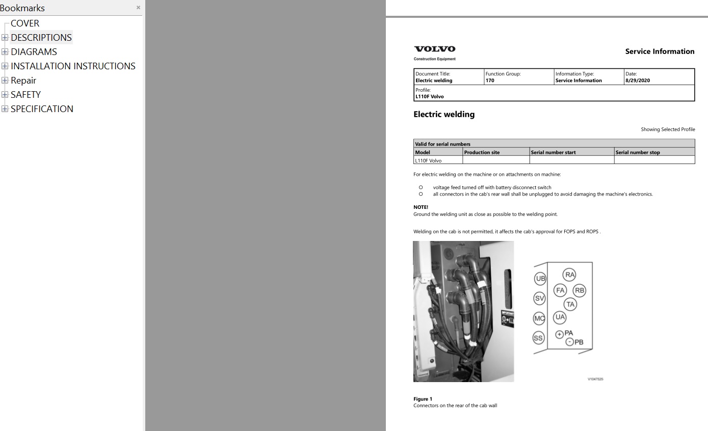
- Electric welding precautions
- Cleanliness requirements for brake and hydraulic systems
- Hydraulic system repair precautions
- Workshop checking points
- Special tools and service references
These topics establish the working practices required before performing mechanical or hydraulic repairs.
2. ENGINE SYSTEM DESCRIPTION
The engine section explains the operation of the major systems responsible for fuel delivery, combustion, cooling, lubrication, and air handling.
ENGINE OPERATION
- Engine general description
- Accelerator pedal
- Hand throttle
- Engine air cleaner
- Preheating system
- Engine cooling system
- Cooling fan
- Cooling fan motor
- Reversible cooling fan
- Engine lubrication system
AIR INTAKE AND EXHAUST
- Intake system description
- Exhaust system description
- Intercooler
- Turbocharger
- Internal Exhaust Gas Recirculation (IEGR)
ELECTRONIC FUEL INJECTION
- Fuel system description
- Fuel feed pump
- Fuel filter
- High-pressure fuel pump
- Fuel rail
- Fuel Control Valve (FCV)
- Fuel injectors
- Instructions for working with electronic fuel injection
3. ENGINE REPAIR AND COMPONENT REPLACEMENT
This part of the manual provides procedures for checking engine condition and servicing individual components.
MECHANICAL ENGINE WORK
- Engine removal
- Engine installation
- Cylinder compression testing
- Cylinder compression testing with VCADS Pro
- Front crankshaft seal replacement
- Engine rotation speed sensor replacement
- Valve adjustment
- Engine idle checks
- Engine stall speed checks
FUEL SYSTEM REPAIRS
- Fuel system bleeding
- Fuel feed pump pressure testing
- Fuel filter inspection
- Fuel Control Valve (FCV) testing
- Fuel Control Valve replacement
- High-pressure fuel pump inspection
- High-pressure fuel pump replacement
- Fuel rail pressure sensor replacement
- Fuel injector replacement
- Pressure Relief Valve (PRV) inspection
- Pressure Relief Valve replacement
- Fuel tank removal and installation
COOLING AND LUBRICATION
- Cooling fan hydraulic function checks
- Cooling fan motor replacement
- Fan control valve removal and installation
- Fan control valve seal replacement
- Radiator removal and installation
- Lubrication oil pressure measurement
- Carbon dioxide checks in the cooling system
- Carbon dioxide checks in the fuel system
ADDITIONAL ENGINE CHECKS
- Turbocharger inspection
- Engine Control Unit (E-ECU) replacement
- E-ECU programming using VCADS Pro
- Engine-related diagnostic operations
4. ELECTRICAL SYSTEM AND ELECTRONIC CONTROL UNITS
The Volvo L110F uses multiple electronic control systems, and the manual provides descriptions and diagnostic references for these components.
ELECTRICAL EQUIPMENT
- Alternator 80 A
- Batteries and charging
- Battery disconnector switch
- Electrical system voltage
- Electrical connectors
- Cable and component identification
- Chassis connections
- Lighting equipment
- Relays and fuses
- Switches and sensors
- Solenoid valves
- PWM valves
ELECTRONIC CONTROL MODULES
- Engine Control Unit (E-ECU)
- Vehicle Control Unit (V-ECU)
- Vehicle Control Unit (V2-ECU)
- Instrument Control Unit (I-ECU)
- Electronic Climate Control (ECC)
- CareTrack W-ECU
The documentation includes input/output lists and functional descriptions for selected control units.
5. ELECTRONIC COMMUNICATION AND TROUBLESHOOTING
The manual includes information about communication between electronic modules and the machine's diagnostic functions.
CONTROL SYSTEM DIAGNOSTICS
- Electronic control system operation
- Communication with data buses
- Bus communication supervision
- Interrupted computer communication
- Reduced computer communication
- ECU booting sequence
- Software parameters
- Troubleshooting strategy
- Electrical connector checks
- Special diagnostic tools
- SAE error code interpretation
INSTRUMENTATION AND INFORMATION DISPLAY
- Engine information
- Transmission information
- Hydraulic system information
- Electrical system information
- Axle and brake information
- Machine operating information
- Vehicle messages
- Service mode
- Information display settings
- Start lockout
- Central warning system
- Alarm descriptions
- Limp-home operation
- Theft protection
6. VCADS PRO SERVICE AND DIAGNOSTIC OPERATIONS
The documentation contains references to VCADS Pro, including diagnostic and programming procedures for selected machine systems.
VCADS PRO INFORMATION
- VCADS Pro service tool
- VCADS Pro error codes
- VCADS Pro operations
- Cylinder compression testing
- Engine idle checks
- Engine stall speed checks
- E-ECU programming
- Central system updating
- Control unit replacement procedures
These sections are particularly relevant when service work involves electronically controlled components.
7. ELECTRICAL WIRING DIAGRAMS
The manual includes a large collection of numbered electrical wiring diagrams.
WIRING DIAGRAM GROUPS
- Diagrams 201–206
- Diagrams 301–319 (selected numbers)
- Diagrams 401–408 (selected numbers)
- Diagram 501
- Diagrams 601, 602 and 604
- Diagrams 801–807 (selected numbers)
- Diagrams 901–915 (selected numbers)
Several diagrams appear in multiple versions within the documentation.
These schematics provide references for tracing electrical connections and investigating problems involving sensors, switches, control units, solenoid valves, and other electrical components.
8. HYDRAULIC TRANSMISSION
The power transmission section describes the hydraulic transmission and includes procedures for checking its operation.
TRANSMISSION DESCRIPTION AND DIAGNOSTICS
- Hydraulic transmission description
- Transmission hydraulic diagram
- Transmission functional checks
- Transmission oil pressure testing
- Transmission calibration error codes
TRANSMISSION REPAIR
- Transmission removal
- Transmission installation
- Transmission pressure sensor replacement
- Transmission solenoid replacement
- Transmission heat exchanger replacement
- Front output shaft seal replacement
- Rear output shaft seal replacement
9. DRIVE AXLES, DIFFERENTIALS AND HUB REDUCTIONS
This section covers the drivetrain components that transmit power to the wheels.
SYSTEM DESCRIPTION
- Drive axle operation
- Differential lock
- Automatic differential brake
- Limited-slip differential
REPAIR OPERATIONS
- Axle removal and installation
- Differential lock adjustment
- Differential lock functional checks
- Hub reduction removal
- Hub reduction installation
- Hub seal replacement
- Axle suspension bushing and seal replacement
10. BRAKING SYSTEM
The brake section contains information for checking hydraulic brake performance, replacing components, and adjusting the parking brake.
BRAKE SYSTEM COMPONENTS
- Brake accumulators
- Foot brake valve
- Wheel brakes
- Parking brake
INSPECTION AND REPAIR PROCEDURES
- Brake accumulator pressure checks
- Brake disc wear measurement
- Brake disc replacement
- Brake piston seal replacement
- Brake pedal angle adjustment
- Brake system circuit pressure testing
- Brake system hydraulic function testing
- Brake retardation function testing
- Brake system bleeding
- Foot brake valve reconditioning
- Foot brake valve removal and installation
- Parking brake pad replacement
- Parking brake disc and seal replacement
- Parking brake adjustment
- Parking brake disassembly and assembly
- Parking brake function testing
- Manual parking brake release
11. STEERING AND COMFORT DRIVE CONTROL
The steering section provides information for servicing the conventional steering system and the optional lever steering equipment.
STEERING SYSTEM
- Steering system description
- Steering valve
- Steering cylinders
- Steering pressure monitoring
- Steering shift valve
- Secondary steering system
COMFORT DRIVE CONTROL (CDC)
- CDC lever steering valve
- CDC angle sensor replacement
- CDC solenoid valve replacement
- CDC servo pressure testing
- CDC functional checks
STEERING REPAIR PROCEDURES
- Steering cylinder removal and installation
- Steering cylinder seal replacement
- Steering cylinder reconditioning
- Steering valve replacement
- Shift valve removal and installation
- Secondary steering pump pressure testing and adjustment
- Steering working pressure testing and adjustment
12. FRAME, AXLE SUSPENSION AND WHEELS
The documentation also covers selected structural and running gear components.
Included topics:
- Frame description
- Frame joint description
- Axle suspension bushing replacement
- Axle suspension seal replacement
- Front wheel removal and installation
- Rear wheel removal and installation
- Frame and wheel tightening torque references
13. OPERATOR CAB AND AIR CONDITIONING
The manual includes service procedures for the cab, heating equipment, air conditioning, and related components.
CAB AND BODY COMPONENTS
- Cab removal and installation
- Engine hood removal and installation
- Manual engine hood operation
- Door lock replacement
- Door lock cylinder replacement
- Viscous cab suspension
- Operator seat securing
- Windscreen replacement
CLIMATE CONTROL
- Air conditioning system description
- Air conditioning troubleshooting
- Electronic Climate Control (ECC)
- Climate unit removal and installation
- Air conditioning compressor replacement
- Condenser replacement
- Evaporator replacement
- Expansion valve replacement
- Receiver replacement
- Heater core replacement
- Heat control valve replacement
- Fan motor replacement
- Air mix door actuator replacement
- Cooling system temperature sensor replacement
14. WORKING HYDRAULIC SYSTEM
The Volvo L110F manual contains extensive hydraulic service information, including pump pressure checks and control valve procedures.
HYDRAULIC SYSTEM DESCRIPTION
- Working hydraulic system operation
- Hydraulic oil tank
- Hydraulic pumps
- Hydraulic pump flow regulation
- Central valve
- Hydraulic control valve
- Pressure monitoring
- Lift function
- Tilt function
- Floating position
- Hydraulic attachment bracket
HYDRAULIC PUMP SERVICE
- Hydraulic pump P1 inspection
- Hydraulic pump P2 inspection
- Hydraulic pump P1 removal and installation
- Hydraulic pump P2 removal and installation
- Hydraulic pump P3 removal and installation
- Hydraulic pump P3 standby pressure testing
- Hydraulic pump P3 maximum pressure checks
- Cooling fan speed adjustment
- Hydraulic pump maximum working pressure adjustment
- Hydraulic pump power control checks
- Hydraulic standby pressure adjustment
15. HYDRAULIC VALVES AND SERVO CONTROL
This section includes procedures for the hydraulic control components.
CONTROL VALVE OPERATIONS
- Central valve removal and installation
- Main control valve removal and installation
- Hydraulic power control valve replacement
- Back-up valve inspection and adjustment
- Back-up valve replacement
- Servo valve removal and installation
- Servo valve control adjustment
SERVO SYSTEM
- Servo accumulator removal and installation
- Servo pressure testing
- Servo pressure adjustment
- Servo pressure checks at the control valve spool
- Hydraulic system bleeding
- Hydraulic system functional testing
16. LIFT AND TILT CYLINDER REPAIRS
The manual provides specific procedures for the wheel loader's lifting and tilting equipment.
LIFTING FUNCTION
- Lift cylinder seal replacement in the machine
- Lift function checks
- Lift and lower angle sensor replacement
- Lift solenoid valve replacement
- Lower solenoid valve replacement
- Lifting time measurement
- Lift shock valve checks
TILTING FUNCTION
- Tilt cylinder seal replacement in the machine
- Tilt function checks
- Tilt angle sensor replacement
- Tilt-in solenoid valve replacement
- Tilt-out solenoid valve replacement
- Tilt shock valve checks
17. BOOM SUSPENSION SYSTEM (BSS)
The Boom Suspension System section contains descriptions and service procedures for its hydraulic components.
Included topics:
- BSS operating description
- BSS component descriptions
- Boom suspension accumulator checks
- Accumulator pressure adjustment
- Accumulator reconditioning
- Hydraulic accumulator depressurization
- Boom suspension safety valve pressure checks
- Boom Suspension System test drive with load
18. THIRD AND FOURTH HYDRAULIC FUNCTIONS
The documentation covers additional hydraulic functions used with compatible equipment configurations.
Included topics:
- Third hydraulic function
- Third and fourth hydraulic functions
- Auxiliary hydraulic pressure testing and adjustment
- Auxiliary hydraulic solenoid valve replacement
- Hydraulic attachment locking
- Hydraulic attachment locking checks
19. AUTOMATIC LUBRICATION AND FIRE SUPPRESSION
The manual includes information for selected auxiliary systems.
AUTOMATIC LUBRICATION
- Central lubrication system description
- Lubrication interval changes
- Lubricant filling
- Automatic lubrication pump reconditioning
- Automatic lubrication system updates
FIRE SUPPRESSION
- Fire suppression system component descriptions
- Fire suppression system operation
- Procedures following automatic activation
- Procedures following manual activation
20. HYDRAULIC CIRCUIT DIAGRAMS
The documentation includes hydraulic diagrams for understanding fluid circuits and component connections.
Included diagrams:
- Hydraulic transmission diagram
- Complete hydraulic system diagrams
- Alternative versions of complete hydraulic diagrams
- Hydraulic diagram explanations
21. OPTIONAL EQUIPMENT INSTALLATION
The manual includes installation instructions for selected additional equipment.
HYDRAULIC EQUIPMENT
- Third hydraulic function installation
- Electro-hydraulic third function installation
- Third and fourth hydraulic function installation
- Hydraulic attachment locking installation
- Boom Suspension System installation
- Automatic lift arm lowering (Return to Dig) installation
- Single-lever control installation
STEERING EQUIPMENT
- Electric CDC lever steering installation
- Hydraulic CDC lever steering installation
ELECTRICAL AND OPERATOR EQUIPMENT
- CareTrack installation
- Forward-view camera installation
- Rear-view camera installation
- Heated and adjustable rear-view mirror installation
- Front and rear work lights
- Attachment work light
- Rotating beacon
ENGINE AND PROTECTION EQUIPMENT
- Engine heater installation
- Additional fuel filter installation
- Hand throttle installation
- Axle oil cooler and reversible fan installation
- Oil-bath air cleaner
- Air pre-cleaner
- Radiator grille guard
- Protective grating
- Front lighting protection
22. WORKSHOP SAFETY INFORMATION
The manual includes safety guidance for maintenance and repair operations.
Topics include:
- General servicing precautions
- Machine handling safety
- Safe lifting and supporting
- Hydraulic system safety
- Hydraulic accumulator precautions
- Battery handling
- Air conditioning refrigerant safety
- Oil and fuel handling
- Tyre safety
- Working beneath a raised boom
- Fire prevention
- Inspection following fire or heat exposure
- Environmental protection
- Waste handling
- Booster battery starting
- Service positions
23. TECHNICAL SPECIFICATIONS
The specifications section provides technical reference information for major machine systems.
ENGINE DATA
- Engine specifications
- Engine capacities
- Fuel system specifications
- Fuel tank volume
- Cooling system volume
- Lubrication system specifications
- Turbocharger tightening torques
- Cooling fan speed specifications
- Thermostat specifications
- Valve system specifications
ELECTRICAL DATA
- Alternator 80 A specifications
- Battery specifications
- Electrical system specifications
- Lighting specifications
- Preheating specifications
TRANSMISSION AND DRIVELINE
- Hydraulic transmission specifications
- Hydraulic transmission oil volume
- Transmission tightening torques
- Front and rear axle specifications
- Axle oil volumes
- Propeller shaft tightening torques
BRAKE AND STEERING
- Brake accumulator specifications
- Brake system specifications
- Parking brake specifications
- Wheel brake specifications
- Steering specifications
- CDC lever steering specifications
- Secondary steering pump specifications
HYDRAULIC SYSTEM
- Hydraulic pump P1 specifications
- Hydraulic pump P2 specifications
- Hydraulic pump P3 specifications
- Hydraulic system volume
- Control valve specifications
- Servo system specifications
- Boom Suspension System specifications
- Third and fourth hydraulic function specifications
ADDITIONAL REFERENCES
- Recommended lubricants and oils
- Alternative fuels
- Air conditioning refrigerant quantities
- Frame and wheel specifications
- General tightening torques
- Conversion tables
PRACTICAL APPLICATIONS
This manual can be used as a reference when performing tasks such as:
- Checking fuel rail pressure-related components
- Inspecting the high-pressure fuel pump
- Replacing fuel injectors
- Testing engine compression
- Investigating ECU communication faults
- Consulting VCADS Pro diagnostic procedures
- Checking transmission oil pressure
- Servicing differential locks and hub reductions
- Measuring brake disc wear
- Adjusting parking brake components
- Checking CDC steering operation
- Testing hydraulic pump output pressures
- Servicing hydraulic control valves
- Replacing lift and tilt cylinder seals
- Checking Boom Suspension System accumulators
- Consulting electrical and hydraulic circuit diagrams
WHO IS THIS MANUAL FOR?
The Volvo L110F Service Repair Manual is intended for:
- Heavy equipment service technicians
- Volvo wheel loader repair specialists
- Independent construction machinery workshops
- Fleet maintenance departments
- Equipment maintenance contractors
- Experienced Volvo L110F owners performing maintenance and repair work
COMPATIBILITY NOTICE
This manual is identified for the Volvo L110F Wheel Loader.
The contents include multiple diagram versions, optional equipment instructions, and procedures for different system configurations.
Before purchasing, confirm your machine model, serial number, and installed equipment to determine whether the documentation matches your machine.
The 2020 information update refers to the supplied technical documentation and should not be interpreted as the manufacturing year of the wheel loader.
DIGITAL DELIVERY
This is a digital PDF service repair manual.
The publication contains:
- 2,039 pages of workshop documentation
- Engine and electronic fuel injection information
- Engine repair and replacement procedures
- Electrical system and ECU descriptions
- VCADS Pro diagnostic references
- Numbered electrical wiring diagrams
- Hydraulic transmission and axle repairs
- Brake system service instructions
- Steering and CDC procedures
- Hydraulic pump pressure adjustments
- Lift and tilt cylinder repair information
- Boom Suspension System procedures
- Hydraulic circuit diagrams
- Equipment installation instructions
- Workshop safety guidance
- Technical specifications and tightening torques
No printed manual will be shipped.
A compatible PDF reader is required to view the documentation.
RELATED VOLVO MANUALS
Looking for more Volvo construction equipment technical documentation?
BROWSE VOLVO WHEEL LOADER MANUALS
Find additional Volvo wheel loader service manuals and parts catalogs.
EXPLORE VOLVO EQUIPMENT MANUALS
Browse technical documentation for other Volvo construction equipment models.
Explore the complete collection of available service repair manuals and parts catalogs.
Please check machine compatibility before purchasing.
Detailed content:
COVER
DESCRIPTIONS
(0) GENERAL
Basic checks
(1) STANDARD PARTS, SERVICE
Charging of batteries
Cleanliness, brake and hydraulic systems
Electric welding (2)
Electric welding
Repairing hydraulic system
Working on the electrical system of the machine
(2) ENGINE WITH MOUNTING AND EQUIPMENT
Accelerator Pedal (2)
Accelerator Pedal
Air cleaner, description
Cooling fan motor, description
Cooling fan, description
Cooling system, description
Engine, description
Fuel control valve (FCV), description
Fuel feed pump, description
Fuel filter, description
Fuel rail, description
Fuel system, description
Hand Throttle
High pressure fuel pump, description
Injectors, description
Instructions for working with electronic fuel injection
Intake and exhaust system, description (2)
Intake and exhaust system, description
Intercooler, description
Internal Exhaust Gas Recirculation (IEGR), description
Lubricating system, description
Preheating, description
Reversible cooling fan, description
Turbocharger, description
(3) ELEC. SYSTEM; WARNING SYSTEM; INFORMATION SYSTEM; INSTRUMENTS
Alarm, description
Alternator 80 A, description
Battery disconnector switch, description
Battery, charging
Battery, description
Booting sequence
Bus communication supervision
Cable and component designations
Cable and component marking explanations (2)
Cable and component marking explanations
CareTrack W-ECU, description
Central warning
Chassis connection
Collection of basic data
Communication with data buses (2)
Communication with data buses
Component list Motors, resistors, monitoring system
Component list Alternator, batteries, capacitors, electronic units, voltage outlet
Component list Fuses
Component list Heating coils, instruments, service socket
Component list Lights (2)
Component list Lights
Component list PWM valves
Component list Relays
Component list Sensors
Component list Signals, shift solenoids
Component list Solenoid valves
Component list Switches
Component list, diodes
Conditions when checking
Connectors, overview
ECC, IO list
E-ECU, IO list
Electrical symbols and designations
Electrical system, description
Electrical system, work instructions
Electronic climate control unit ECC, description
Electronic control system, description
Engine control unit E-ECU, description
Fuel consumption
General fault diagnosis information
I-ECU, IO list
Information display, axles brakes (2)
Information display, axles brakes
Information display, check (2)
Information display, check
Information display, electrical system (2)
Information display, electrical system
Information display, engine
Information display, general
Information display, hydraulics (2)
Information display, hydraulics
Information display, operating display
Information display, service (2)
Information display, service mode (2)
Information display, service mode
Information display, service
Information display, settings
Information display, start lockout
Information display, transmission
Information display, vehicle info
Information display, vehicle messages
Instrument control unit I-ECU, functional description
Instrument panels
Intermittent wiper and washer
Interruption in computer communication
Key feed
Lead and connector checks
Lighting, description
Limp Home
Machine hours
Middle instrument panel with warning lights
Reduced computer communication
SAE error codes, translation to error messages, general
Software parameters, description
Software, description
Special tools for troubleshooting
System voltage
Theft protection
Travelling speed
Troubleshooting strategy
Troubleshooting tools
V2-ECU, IO list
VCADS Pro service tool
VCADS Pro, Error codes
V-ECU, IO list
Vehicle control unit V2-ECU, description
Vehicle control unit V-ECU, description
Washer fluid level
(4) POWER TRANSMISSION
Automatic differential brake, Limited Slip, description
Differential lock, description (2)
Differential lock, description
Drive axles, description
Hydraulic transmission, description
(5) BRAKE
Brake accumulator, description
Braking system, description
Foot brake valve, description
Parking brake, component description
Parking brake, description
Parking brake, function description
Tightening torque
(6) STEERING
CDC valve, lever steering, description
Pressure monitor, description
Shift valve, description
Steering cylinder, description
Steering system, description
Steering valve, description
(7) FRAME; SPRINGS; DAMPING; AXLE SUSPENSION; WHEEL, TRACK UNIT
Frame joint, description
Frame, description
(8) MACHINERY HOUSE; CAB; EXTERIOR TRIM PARTS ANYWHERE
Air conditioning, description
Pause heater, description (2)
Pause heater, description
Troubleshooting, air conditioning unit (AC)
Viscous cab suspension, description
Windows, general
(9) HYDRAULIC SYSTEM, DIGGING, HANDLING, GRADING EQUIPM, MISC. EQUIP
3rd, alternatively 3rd 4th hydraulic function, description
Boom Suspension System, component description
Boom Suspension System, description
Central lubrication system, description
Central valve, description
Change of lubrication interval
Control valve, description (2)
Control valve, description (3)
Control valve, description
Diagnostic tools, description
Dosage valves, description
Filling lubricant
Fire suppression system, component description
Fire suppression system, functional description
Floating position, description
Hydraulic attachment bracket, description
Hydraulic components, cleanliness when handling
Hydraulic oil tank, description
Hydraulic pump flow regulation, description
Hydraulic pumps, description
Hydraulic system, description
Lift function, description (2)
Lift function, description
Parameter settings
Pressure monitor, description
Pump unit, description
Shift valve, description
Software, parameter settings and read-outs
Tilt function, description
TP-Linkage’s bearing points
Working hydraulic system, function description
DIAGRAMS
(3) ELEC. SYSTEM; WARNING SYSTEM; INFORMATION SYSTEM; INSTRUMENTS
Table of contents, wiring diagrams
Wiring diagram 201
Wiring diagram 202
Wiring diagram 203
Wiring diagram 204
Wiring diagram 205
Wiring diagram 206
Wiring diagram 301 (2)
Wiring diagram 301
Wiring diagram 302 (2)
Wiring diagram 302 (3)
Wiring diagram 302
Wiring diagram 303
Wiring diagram 304 (2)
Wiring diagram 304
Wiring diagram 305
Wiring diagram 306 (2)
Wiring diagram 306 (3)
Wiring diagram 306
Wiring diagram 308
Wiring diagram 309
Wiring diagram 310
Wiring diagram 311 (2)
Wiring diagram 311 (3)
Wiring diagram 311
Wiring diagram 312
Wiring diagram 313
Wiring diagram 314 (2)
Wiring diagram 314
Wiring diagram 315 (2)
Wiring diagram 315 (3)
Wiring diagram 315
Wiring diagram 316
Wiring diagram 317
Wiring diagram 319
Wiring diagram 401 (2)
Wiring diagram 401
Wiring diagram 402
Wiring diagram 403 (2)
Wiring diagram 403
Wiring diagram 404
Wiring diagram 407
Wiring diagram 408 (2)
Wiring diagram 408
Wiring diagram 501 (2)
Wiring diagram 501
Wiring diagram 601 (2)
Wiring diagram 601
Wiring diagram 602 (2)
Wiring diagram 602
Wiring diagram 604 (2)
Wiring diagram 604
Wiring diagram 801
Wiring diagram 802
Wiring diagram 804 (2)
Wiring diagram 804
Wiring diagram 805 (2)
Wiring diagram 805
Wiring diagram 806 (2)
Wiring diagram 806
Wiring diagram 807
Wiring diagram 901 (2)
Wiring diagram 901
Wiring diagram 902 (2)
Wiring diagram 902
Wiring diagram 903
Wiring diagram 904 (2)
Wiring diagram 904
Wiring diagram 908
Wiring diagram 909
Wiring diagram 910
Wiring diagram 911 (2)
Wiring diagram 911
Wiring diagram 912 (2)
Wiring diagram 912
Wiring diagram 913
Wiring diagram 915
(4) POWER TRANSMISSION
Hydraulic diagram transmission
(9) HYDRAULIC SYSTEM, DIGGING, HANDLING, GRADING EQUIPM, MISC. EQUIP
Explanations to hydraulic diagram
Hydraulic diagram, complete (2)
Hydraulic diagram, complete (3)
Hydraulic diagram, complete (4)
Hydraulic diagram, complete
INSTALLATION INSTRUCTIONS
3rd 4th hydraulic function, installing new
3rd hydraulic function, electric-hydraulic, installing new
3rd hydraulic function, installing new
Attachment locking, installing new
Attachment work light, installing new
Automatic lift arm lowering (Return to dig), installing new
Axle oil cooler and reversilble fan, installing new
Boom suspension system, installing new
Cab, air pre cleaner, installing new
CARE TRACK (2)
CARE TRACK
El. heated and adjustible rear view mirror
Engine heater, installing new (2)
Engine heater, installing new
Forward view camera, installing new
Front view mirror, installing new
Fuel filter extra, installing new
Hand throttle, installing new
heater
Lever steering (CDC), electric, installing new (2)
Lever steering (CDC), electric, installing new
Lever steering (CDC), hydraulic, installing new (2)
Lever steering (CDC), hydraulic, installing new
Oil-bath air cleaner
Pre-cleaner
PROTECTING GRATING
Protection for lighting, front, installing new
Radiator grille guard, installing new
Rear view camera, installing new
Rotating beacon, installing new
Single lever control, installing new (2)
Single lever control, installing new
Work light front, installing new
Work light rear, installing new (2)
Work light rear, installing new
Repair
(0) GENERAL
E 1708, Checking point
E1706
E-2000
E-2001
E-2015
E-2017
Infrared Thermometer
Operation numbers for additional work
(1) STANDARD PARTS, SERVICE
Boom suspension accumulator, checking and adjusting
Brake discs, measuring wear 2
Brake discs, measuring wear
Hydraulic pump P1 and P2, checking
Hydraulic pump, max working pressure, checking and adjusting 2
Hydraulic pump, max working pressure, checking and adjusting
Parking brake, manually releasing 2
Parking brake, manually releasing
Steering system working pressure, checking and adjusting .3
Steering system working pressure, checking and adjusting 2
Steering system working pressure, checking and adjusting
Towing
Transmission oil pressure, checking 2
Transmission oil pressure, checking 3
Transmission oil pressure, checking 4
Transmission oil pressure, checking 5
Transmission oil pressure, checking 6
Transmission oil pressure, checking
(2) ENGINE WITH MOUNTING AND EQUIPMENT
Carbon dioxide in coolant system, checking
Carbon dioxide in fuel system, checking
Cooling fan hydraulics, funktion check
Cooling fan motor, replacing
Crankshaft seal, front, changing
Cylinder compression, testing 2
Cylinder compression, testing
Cylinder compression, VCADS Pro 2
Cylinder compression, VCADS Pro
E-ECU MID 128 non-programmed, replacing
E-ECU MID 128 pre-programmed, replacing
Engine rotation speed sensor, replacing
Engine, installing (2)
Engine, installing
Engine, removing 2
Engine, removing
Fan control valve, installing
Fan control valve, removing
Fan control valve, seal replacing
Feed pump pressure, checking
Fuel control valve (FCV), checking
Fuel control valve (FCV), replacing
Fuel filter, checking
Fuel rail pressure sensor, replacing
Fuel system, bleeding
Fuel tank, installing
Fuel tank, removing
High pressure fuel pump, checking
High pressure fuel pump, replacing
Idle, VCADS Pro
Injectors, replacing 2
Injectors, replacing
Lubrication oil pressure, checking with pressure gauge
Pressure relief valve (PRV), inspecting
Pressure relief valve (PRV), replacing
Pump 3 (P3) standby pressure, checking and adjusting (LS-line removed)
Pump 3 (P3), max pressure and fan speed, checking and adjusting
Radiator, installing
Radiator, removing
Stall speed, checking
Stall speed, VCADS Pro
Turbocharger, inspecting
Valves, adjusting
VCADS Pro, central systems updating, replace component
VCADS Pro, MID 128, programming E-ECU
(3) ELEC. SYSTEM; WARNING SYSTEM; INFORMATION SYSTEM; INSTRUMENTS
Batteries, replacing
Battery condition, checking
I-ECU MID 140 non-programmed, replacing
I-ECU MID 140 pre-programmed, replacing
Starter lock, replacing
VCADS Pro, Operations
V-ECU MID 187 non-programmed, replacing
V-ECU MID 187 pre-programmed, replacing
(4) POWRER TRANSMISSION
Axle, installing
Axle, removing
Differential lock, adjusting
Differential lock, function check
Error codes when calibrating
Heat exchanger, replacing
Hub reduction, installing 2
Hub reduction, installing
Hub reduction, removing 2
Hub reduction, removing
Hub seal, replacing 2
Hub seal, replacing
Seal for front output shaft, replacing
Seal for rear output shaft, replacing
Transmission oil pressure, checking
Transmission pressure sensor, replacing
Transmission solenoid, replacing
Transmission, functional check
Transmission, installing
Transmission, removing
(5) BRAKE
Accumulator (removed) charging pressure, checking
Accumulator, checking
Accumulator, discarding
Brake disc, replacing
Brake discs, measuring wear 2
Brake discs, measuring wear
Brake discs, replacing 2
Brake discs, replacing
Brake pedal, adjusting angle
Brake piston seals, replacing 2
Brake piston seals, replacing 3
Brake piston seals, replacing 4
Brake piston seals, replacing
Brake system circuit pressure, checking and adjusting
Brake system hydraulic function, checking
Brake system retardation function, checking
Brake system, bleeding
Foot brake valve removed, reconditioning
Foot brake valve, installing
Foot brake valve, removing
Parking brake assembly, removing
Parking brake brake pads, replacing
Parking brake discs and seals, replacing
Parking brake function, checking 2
Parking brake function, checking
Parking brake, adjusting
Parking brake, assembling
Parking brake, disassembling
Parking brake, installing
(6) STEERING
Accumulator, discarding
Comfort drive control (CDC) angle sensor, changing
Comfort drive control (CDC) solenoid valve, changing
Comfort Drive Control, servo pressure, checking
Error codes when calibrating
Lever steering (CDC) function, checking
Secondary steering pump working pressure, checking and adjusting
Shift valve, installing
Shift valve, removing
Steering cylinder removed, reconditioning excl replacing bearings
Steering cylinder, installing
Steering cylinder, removing
Steering cylinder, repacking
Steering system function, checking
Steering system working pressure, checking and adjusting
Steering valve, replacing
(7) FRAME;SPRINGS;DAMPING;AXLE SUSPENSION; WHEEL TRACK UNIT
Axle suspension, replacing bushes and seals
Front wheel, installing
Front wheel, removing
Rear wheel, installing
Rear wheel, removing 2
Rear wheel, removing
(8) MACHINERY HOUSE;CAB;EXTERIOR TRIM PARTS ANYWHERE
Air mix door actuator, replacing
Cab, installing 2
Cab, installing 3
Cab, installing
Cab, removing 2
Cab, removing 3
Cab, removing
Climate unit, installing
Climate unit, removing
Compressor, replacing incl draining and filling
Condenser, replacing incl draining and filling
Door lock cylinder, replacing 2
Door lock cylinder, replacing
Door lock, replacing
ECC (Electronic Climate Control), replacing 2
ECC (Electronic Climate Control), replacing
ECC MID 146 non-programmed ECU, replacing
ECC MID 146 pre-programmed ECU, replacing
Engine hood, installing
Engine hood, manually operating
Engine hood, removing
Evaporator, replacing incl draining and filling 2
Evaporator, replacing incl draining and filling
Expansion valve, replacing incl draining and filling
Fan motor, replacing
Heat control valve, replacing
Heater core, replacing 2
Heater core, replacing
Operator’s seat, securing
Receiver, replacing incl draining and filling 2
Receiver, replacing incl draining and filling
Temperature sensor cooling system, replacing
Viscous cab suspension, changing one unit
Windscreen, replacing 2
Windscreen, replacing
(9) HYDRAULIC SYSTEM;DIGGING HANDING GRANDING EQUIPM.; MISC. EQUIP
3rd 4th hydraulic function, pressure, checking and adjusting
3rd 4th hydraulic function, solenoid valve, replacing
Accumulator removed, checking
Accumulator, boom suspension system, discarding
Accumulator, checking (pressure back-up for servo circuit)
Accumulator, discarding (2)
Accumulator, discarding
Attachment locking, checking
Automatic lubrication pump unit, reconditioning
Back-up valve, checking and adjusting
Back-up valve, replacing
Bleeding air
Boom suspension accumulator, checking and adjusting
Boom suspension accumulator, reconditioning
Boom suspension system, hydraulic oil pressure in accumulators, depressurizing
Boom suspension system, pressure reduction, safety valve, checking and adjusting
Boom suspension system, test drive with load
Central valve, installing
Central valve, removing
Control valve, installing
Control valve, removing
Error codes when calibrating
Fire suppression system, actions after activation
Fire suppression system, actions after manual activation
Hydraulic oil tank, vacuum-pumping, connecting and disconnecting pump
Hydraulic power control valve, replacing
Hydraulic pump P1 and P2, checking
Hydraulic pump P1, installing
Hydraulic pump P1, removing
Hydraulic pump P2, installing
Hydraulic pump P2, removing
Hydraulic pump P3, installing
Hydraulic pump P3, removing
Hydraulic pump, max working pressure, checking and adjusting
Hydraulic pump, power control, checking
Hydraulic pump, standby pressure and working pressure, checking and adjusting
Hydraulic pump, standby pressure, checking and adjusting
Hydraulic system, bleeding
Lift cylinder, repacking in machine
Lift lower, angle sensor, changing 2
Lift lower, angle sensor, changing
Lift, functional check
Lift, solenoid valve, changing
Lifting time, checking
Lower, solenoid valve, changing
Servo accumulator, installing
Servo accumulator, removing
Servo pressure, at the spool in control valve, checking
Servo pressure, checking and adjusting
Servo valve, control, adjusting
Servo valve, installing
Servo valve, removing
Shock valve lift function, checking 2
Shock valve lift function, checking
Shock valve, tilt function, checking
System test
Tilt cylinder, repacking in machine
Tilt in out, angle sensor, changing
Tilt in, solenoid valve, changing
Tilt out, solenoid valve, changing
Tilt, checking
Update of automatic lubrication system
V2-ECU, MID 249, changing non-programmed ECU
V2-ECU, MID 249, changing pre-programmed ECU
SAFETY
(1) STANDARD PARTS, SERVICE
CE-marking, EMC-directive
Checking function
Checklist after a fire or heat exposure
Decontamination
Environmental handling for the future
Environmentally hazardous fluids
Environmentally safe handling
Fire prevention measures
Health hazards with paint, plastics and rubber
Safety concerns everybody! (2)
Safety concerns everybody!
Safety rules when servicing
Safety when handling accumulators
Safety when handling oils and fuel
Safety when handling the machine
Safety when lifting and supporting complete machine
Safety when using lifting equipment
Safety when working on hydraulic systems
Safety when working with air conditioning refrigerant
Safety when working with batteries
Service position 1 (2)
Service position 1
Service position 2 (2)
Service position 2
Some simple rules regarding tyre handling (2)
Some simple rules regarding tyre handling
Starting with booster batteries
Waste handling
Working in environmentally contaminated areas
Working under raised boom
(9) HYDRAULIC SYSTEM, DIGGING, HANDLING, GRADING EQUIPM, MISC. EQUIP
Safety when working on hydraulic systems
SPECIFICATION
(0)GENERAL
3rd 4th hydraulic function, specifications
Air conditioning, refrigerant, weight (2)
Air conditioning, refrigerant, weight
Air conditioning, tightening torques
Alternator 80 A, specification
Battery, specifications
Battery, weight
Boom Suspension System, specifications
Boom Suspension System, tightening torques
Brake accumulator, specifications
Brake system, specifications
Brake valve, tightening torques
Cab, tightening torque
Control valve, lever steering (CDC), specifications
Control valve, specifications
Conversion tables (2)
Conversion tables
Cooling fan rpm, specifications (2)
Cooling fan rpm, specifications
Cooling system, volume
Electrical system, specifications
Engine, capacities
Engine, specifications (2)
Engine, specifications (3)
Engine, specifications
Frame joint, tightening torques
Frame, tightening torque
Front and rear axles, specifications (2)
Front and rear axles, specifications
Front and rear axles, tightening torque
Front and rear axles, volume
Fuel feed pump, specifications
Fuel system, specifications
Fuel system, tightening torques
Fuel tank, volume
Hydraulic connections, tightening torques
Hydraulic pump (P1), specifications
Hydraulic pump (P2), specifications
Hydraulic pump (P3), specifications
Hydraulic system, volume
Hydraulic transmission, specifications
Hydraulic transmission, tightening torques
Hydraulic transmission, volume (2)
Hydraulic transmission, volume
Lever steering (CDC), specifications
Lift cylinder, tightening torques
Lubrication system, specifications
Oil sump, tightening torque
Parking brake, specifications (2)
Parking brake, specifications
Preheating, specifications
Propeller shaft, tightening torque
Rear axle mounting, volume
Reversible cooling fan, tightening torques
Secondary steering pump, specifications
Servo system, specifications
Speed sensor, specifications
Speed sensor, tightening torque
Steering cylinder, tightening torque
Steering, specifications
Temperature limits for cooling fan speed, specifications.
Thermostat, specifications (2)
Thermostat, specifications
Tightening torques
Tilt cylinder, tightening torques
Turbocharger, tightening torques
Valve system specifications
Wheel brake, specification
Wheel brake, tightening torques
Wheel, tightening torque
Wheels, specifications
(1) STANDARD PARTS, SERVICE
Alternative fuels
Recommended lubricants, oils
Wheel brake, specification (2)
Wheel brake, specification
(2) ENGINE WITH MOUNTING AND EQUIPMENT
Cooling fan rpm, specifications
Cooling system, volume
Engine, capacities
Engine, specifications (2)
Engine, specifications
Fuel feed pump, specifications
Fuel system, specifications
Fuel system, tightening torques
Fuel tank, volume
Hydraulic pump (P3), specifications
Lubrication system, specifications
Oil sump, tightening torque
Reversible cooling fan, tightening torques (2)
Reversible cooling fan, tightening torques
Temperature limits for cooling fan speed, specifications.
Thermostat, specifications
Valve system specifications (2)
Valve system specifications
(3) ELEC. SYSTEM; WARNING SYSTEM; INFORMATION SYSTEM; INSTRUMENTS
Alternator 80 A, specification
Battery, specifications
Battery, weight
Electrical system, specifications
Lighting, specifications
Preheating, specifications
(4) POWRER TRANSMISSION
Front and rear axles, specifications
Front and rear axles, tightening torque
Front and rear axles, volume (2)
Front and rear axles, volume
Hydraulic transmission, specifications
Hydraulic transmission, tightening torques
Hydraulic transmission, volume (2)
Hydraulic transmission, volume
Propeller shaft, tightening torque
(5) BRAKE
Brake accumulator, specifications
Brake system, specifications
Brake valve, tightening torques
Parking brake, specifications (2)
Parking brake, specifications
Wheel brake, specification (2)
Wheel brake, specification
Wheel brake, tightening torques
(6) STEERING
Control valve, lever steering (CDC), specifications
Lever steering (CDC), specifications
Secondary steering pump, specifications
Steering cylinder, tightening torque
Steering, specifications
(7) FRAME;SPRINGS;DAMPING;AXLE SUSPENSION; WHEEL TRACK UNIT
Axle suspension, tightening torque
Counterweight, tightening torques
Frame joint, tightening torques
Frame, specifications
Frame, tightening torque
Wheel, tightening torque
Wheels, specifications
(8) MACHINERY HOUSE;CAB;EXTERIOR TRIM PARTS ANYWHERE
Air conditioning, refrigerant, weight 2
Air conditioning, refrigerant, weight
Air conditioning, specifications
Air conditioning, tightening torques
Cab, tightening torque
Cabin, tightening torques
(9) HYDRAULIC SYSTEM;DIGGING HANDING GRANDING EQUIPM.; MISC. EQUIP
3rd 4th hydraulic function, specifications
Automatic lubrication system, specifications
Boom Suspension System, tightening torques
Control valve, specifications
Fire suppression system, specification
Function times, specifications
Hydraulic connections, tightening torques
Hydraulic pump (P1), specifications
Hydraulic pump (P2), specifications
Hydraulic system, volume
Lift cylinder, tightening torques
Recommended lubricants
Servo system, specifications
Tilt cylinder, tightening torques
More products


