$14.50
VOLVO L120H WHEEL LOADER WORKSHOP REPAIR SERVICE MANUAL PDF – 2474 PAGES
Technical Documentation for Workshop Maintenance and Repairs
The Volvo L120H Wheel Loader Workshop Repair Service Manual is an extensive 2,474-page technical publication covering the machine's major mechanical, electrical, electronic, transmission, steering, braking, and hydraulic systems.
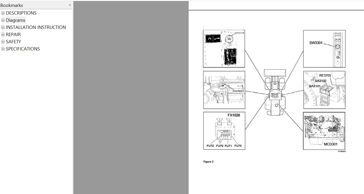
Published in 2020, this PDF manual brings together workshop information organized into system descriptions, technical diagrams, installation instructions, repair documentation, safety information, and specifications.
One of the most substantial features of this publication is its large collection of electrical wiring diagrams, including dedicated circuits for exhaust aftertreatment, braking, Boom Suspension System (BSS), Comfort Drive Control (CDC), gear controls, starting equipment, and electrically controlled battery disconnectors.
The documentation also includes hydraulic diagrams for the transmission, basic machine configurations, and complete hydraulic systems, with multiple versions of selected diagrams.
Beyond the main machine systems, the manual contains installation instructions for a wide range of equipment, including CareTrack, axle oil coolers, auxiliary hydraulic functions, reversible fans, LED work lights, cameras, warning devices, and optional control systems.
For professional technicians, maintenance departments, and experienced equipment owners, this publication provides a structured source of technical information for identifying systems, consulting diagrams, reviewing repair documentation, and checking equipment configurations.
MANUAL INFORMATION
- Manufacturer: Volvo Construction Equipment
- Equipment Model: Volvo L120H Wheel Loader
- Manual Type: Workshop Repair Service Manual
- Publication Year: 2020
- Document Format: PDF
- Total Pages: 2,474
- Delivery: Digital Download
TECHNICAL CONTENT OVERVIEW
The manual is organized into six main documentation categories:
- Descriptions
- Diagrams
- Installation Instructions
- Repair
- Safety
- Specifications
These sections cover the Volvo L120H's principal machine systems, as well as selected optional equipment and configuration-specific documentation.
1. GENERAL MACHINE AND SERVICE INFORMATION
The general and standard service sections form the foundation of the workshop documentation.
Main coverage:
- General machine information
- Standard parts and service
- Service-related technical descriptions
- General repair documentation
- Standard service specifications
- Safety information associated with servicing
2. ENGINE AND ASSOCIATED EQUIPMENT
The manual includes dedicated descriptions, repair documentation, and specifications for the engine and its associated equipment.
Covered documentation groups:
- Engine with mounting and equipment
- Engine system descriptions
- Engine-related repair information
- Engine technical specifications
- Installation instructions for selected engine-related accessories
Engine-related optional equipment includes:
- Engine heater
- Hand throttle
- Reversible fan
- High-sulphur fuel conversion kit
- Cyclone-type air pre-cleaner
- Oil-bath air pre-cleaner
- Turbo-type air pre-cleaner
- Cab air pre-cleaner
The publication includes multiple installation instruction entries for selected components, including engine heaters and reversible fans.
3. ELECTRICAL SYSTEM, WARNING SYSTEM AND INSTRUMENTATION
A major part of the manual is devoted to the machine's electrical and electronic equipment.
Documentation covers:
- Electrical system
- Warning system
- Information system
- Instruments
- Electrical system descriptions
- Electrical repair documentation
- Electrical system specifications
- Electrical wiring diagrams
The wiring diagram collection includes dedicated circuits for several important machine functions.
4. EXHAUST AFTERTREATMENT ELECTRICAL DIAGRAMS
The publication contains specific wiring diagrams for the exhaust aftertreatment system.
Included diagrams:
- Wiring Diagram – Aftertreatment
- Wiring Diagram – Aftertreatment (2)
These provide electrical circuit references for the aftertreatment system.
5. BRAKING SYSTEM ELECTRICAL DOCUMENTATION
The manual includes electrical and technical documentation for the braking system.
Included coverage:
- Brake system descriptions
- Brake repair documentation
- Brake specifications
- Dedicated brake wiring diagram
- Related numbered electrical diagrams
6. BOOM SUSPENSION SYSTEM (BSS)
The Boom Suspension System is represented in the manual's electrical diagrams and optional equipment installation instructions.
Included documentation:
- BSS wiring diagram
- Boom Suspension System installation instructions
- Related hydraulic system documentation
- Machine system descriptions and repair sections
7. COMFORT DRIVE CONTROL (CDC)
The manual includes documentation for Comfort Drive Control, including electrical diagrams and installation instructions.
Included topics:
- CDC wiring diagram
- Electric lever steering installation
- Additional version of electric CDC installation instructions
- Steering system descriptions
- Steering repair documentation
- Steering specifications
8. BATTERY DISCONNECTOR AND EMERGENCY STOP CIRCUITS
The electrical diagram collection includes several configurations of the battery disconnector system.
Dedicated wiring diagrams:
- Electrically controlled battery disconnector – Key operated, with emergency stop
- Electrically controlled battery disconnector – Manual, with emergency stop
- Electrically controlled battery disconnector – Manual, without emergency stop
The installation section also includes instructions for fitting an emergency stop system.
9. GEAR CONTROL AND STARTING CIRCUITS
The manual provides separate wiring diagrams for gear control and starting functions.
Included diagrams:
- Wiring Diagram – Gear
- Wiring Diagram – Start
Additional numbered diagrams are provided in the main electrical diagram collection.
10. EXTENSIVE NUMBERED ELECTRICAL WIRING DIAGRAMS
One of the strongest features of this manual is its extensive selection of WD-series wiring diagrams.
The collection includes the following diagram groups.
WD200 SERIES
- WD201–WD202
- WD260–WD266
- WD268–WD270
WD300 SERIES
- WD301–WD306
- WD320–WD322
- WD324–WD327
- WD330–WD331
- WD333–WD335
- WD337
- WD350–WD352
- WD360–WD363
- WD371–WD376
WD400 SERIES
- WD401–WD406
WD500 AND WD600 SERIES
- WD501
- WD601–WD602
- WD604
WD800 SERIES
- WD801–WD802
- WD804–WD808
- WD831
WD900 SERIES
- WD901–WD904
- WD908–WD913
- WD915
Several diagrams are included in multiple versions, such as WD301, WD320, WD322, WD360, WD802, and WD913.
This collection offers technical references for identifying electrical circuits and comparing diagram versions associated with different configurations.
11. POWER TRANSMISSION SYSTEM
The manual contains technical documentation for the power transmission.
Included documentation:
- Power transmission descriptions
- Power transmission repair information
- Power transmission specifications
- Hydraulic transmission diagrams
HYDRAULIC TRANSMISSION DIAGRAMS
- Hydraulic Diagram – Transmission
- Hydraulic Diagram – Transmission (2)
These diagrams provide references for the transmission hydraulic circuits.
12. STEERING SYSTEM
The steering section includes descriptions, repair documentation, and technical specifications.
Included coverage:
- Steering system descriptions
- Steering repair information
- Steering specifications
- CDC wiring diagram
- Electric CDC installation instructions
- Related hydraulic system diagrams
13. FRAME, SUSPENSION AND WHEEL EQUIPMENT
The manual contains a dedicated section for the machine's structural and running gear systems.
Covered documentation categories:
- Frame
- Springs and damping
- Axle suspension
- Wheel and track unit
- Repair documentation
- Technical specifications
14. CAB, MACHINE SUPERSTRUCTURE AND EXTERIOR EQUIPMENT
The cab and exterior equipment section provides descriptions, repair information, and specifications.
Documentation groups:
- Cab
- Machinery house
- Exterior trim parts
- Cab-related repairs
- Cab and exterior equipment specifications
Related optional equipment installation:
- Cab LED work lights
- Cab entrance illumination
- Rear-view mirrors
- Radio
- Cab air pre-cleaner
- Forward-view camera
- Warning beacons
15. WORKING HYDRAULIC SYSTEM
The hydraulic system section covers the machine's digging, handling, grading, and auxiliary equipment.
Documentation includes:
- Hydraulic system descriptions
- Hydraulic repair information
- Hydraulic system specifications
- Hydraulic diagram explanations
- Basic machine hydraulic diagrams
- Complete hydraulic diagrams
16. BASIC MACHINE HYDRAULIC DIAGRAMS
The publication includes multiple versions of the basic machine hydraulic diagram.
Included diagrams:
- Hydraulic Diagram – Basic Machine
- Hydraulic Diagram – Basic Machine (2)
- Hydraulic Diagram – Basic Machine (3)
These provide hydraulic circuit references for the basic machine configurations represented in the publication.
17. COMPLETE HYDRAULIC SYSTEM DIAGRAMS
The manual also includes several versions of the complete hydraulic system diagram.
Included diagrams:
- Hydraulic Diagram – Complete
- Hydraulic Diagram – Complete (2)
- Hydraulic Diagram – Complete (3)
An additional section explains the symbols and references used in the hydraulic diagrams.
18. AUXILIARY HYDRAULIC FUNCTIONS AND ATTACHMENT LOCKING
The installation documentation includes procedures for adding selected hydraulic functions and control equipment.
Included installation instructions:
- Third hydraulic function
- Hydraulic attachment locking
- Multi-lever control for the third hydraulic function
- Multi-lever control for the fourth hydraulic function
- Single-lever control for the second hydraulic function
- Single-lever control for the third hydraulic function
- Single-lever control for the fourth hydraulic function
19. AXLE OIL COOLER AND COOLING EQUIPMENT
The manual contains installation instructions for selected cooling-related accessories.
Included topics:
- Axle oil cooler installation
- Additional axle oil cooler installation version
- Reversible fan installation
- Additional reversible fan installation version
- Radiator grille guard installation
20. CARETRACK AND CAMERA EQUIPMENT
The optional equipment section includes installation information for selected electronic monitoring and visibility equipment.
Included instructions:
- CareTrack installation
- Forward-view camera installation
- Rear-view mirror installation
- Reverse warning system installation
- Backup alarm installation
21. LED WORK LIGHTING AND WARNING DEVICES
The publication includes installation instructions for a wide range of lighting and warning equipment.
LED WORK LIGHTS
- Cab front LED work light
- Cab rear LED work light
- Cab side LED work light
- Front LED work light
- Grille LED work light
- Illuminated cab entrance
WARNING EQUIPMENT
- Rotating beacon
- Flashing strobe warning beacon
- Seat belt LED beacon
- Reverse warning system
- Backup alarm
22. ENGINE ACCESSORIES AND AIR PRE-CLEANERS
The manual includes instructions for fitting selected engine accessories and air intake equipment.
Included installations:
- Engine heater
- Hand throttle
- High-sulphur fuel conversion kit
- Cyclone-type pre-cleaner
- Oil-bath pre-cleaner
- Turbo-type pre-cleaner
- Cab air pre-cleaner
Some installations are represented by more than one instruction entry.
23. ADDITIONAL MACHINE ACCESSORIES
The installation section also includes documentation for:
- Decal set
- Radio
- Rear-view mirror
- Radiator grille guard
- Emergency stop
- Cab entrance illumination
- Additional work lighting
24. REPAIR DOCUMENTATION
The publication contains a dedicated repair category covering the main machine systems.
Repair documentation is organized under:
- General
- Standard parts and service
- Engine with mounting and equipment
- Electrical, warning and information systems
- Power transmission
- Brakes
- Steering
- Frame and axle suspension
- Cab and exterior equipment
- Hydraulic and working equipment
The supplied table of contents identifies these repair categories but does not list every individual repair operation.
25. SAFETY INFORMATION
The manual includes a dedicated safety category under standard parts and service.
This section provides the safety documentation associated with workshop operations.
26. TECHNICAL SPECIFICATIONS
The specifications section covers the major machine systems.
Specification categories include:
- General machine specifications
- Standard parts and service
- Engine and related equipment
- Electrical and electronic systems
- Power transmission
- Brakes
- Steering
- Frame and axle suspension
- Cab and exterior equipment
- Hydraulic and working equipment
WHY THIS MANUAL IS A VALUABLE WORKSHOP REFERENCE
The Volvo L120H combines mechanical systems with extensive electrical controls and hydraulic equipment.
This publication provides a centralized technical reference for these systems, with particular value in its collection of electrical and hydraulic diagrams.
The manual can help users:
- Locate machine system descriptions
- Consult dedicated aftertreatment wiring diagrams
- Identify brake and CDC electrical circuits
- Review BSS-related documentation
- Examine battery disconnector configurations
- Compare numbered wiring diagram versions
- Reference transmission hydraulic circuits
- Study basic and complete hydraulic diagrams
- Review optional equipment installation instructions
- Locate repair documentation by system
- Consult safety information
- Find technical specifications
INTENDED USERS
This workshop publication is suitable for:
- Volvo construction equipment technicians
- Professional wheel loader mechanics
- Independent heavy equipment repair workshops
- Construction machinery maintenance departments
- Fleet service teams
- Experienced Volvo L120H owners responsible for maintenance and repair work
IMPORTANT COMPATIBILITY NOTICE
This manual is identified for the Volvo L120H Wheel Loader.
The documentation includes multiple electrical wiring diagram versions, hydraulic diagram variants, and installation instructions for optional equipment.
Not every circuit or installation procedure necessarily applies to every machine configuration.
Before purchasing, verify your equipment model, serial number, and installed options to determine whether the relevant documentation matches your machine.
The 2020 date is the publication year of the manual, not necessarily the manufacturing year of the equipment.
DIGITAL PDF DELIVERY
This product is supplied as a digital PDF workshop manual.
The publication includes:
- 2,474 pages of technical documentation
- Machine system descriptions
- Engine and related equipment documentation
- Electrical system and instrumentation information
- Extensive WD-series electrical wiring diagrams
- Aftertreatment wiring diagrams
- Brake, BSS and CDC wiring diagrams
- Battery disconnector and emergency stop circuits
- Transmission hydraulic diagrams
- Basic machine hydraulic diagrams
- Complete hydraulic system diagrams
- Auxiliary hydraulic equipment installation instructions
- CareTrack and camera installation information
- LED lighting and warning device installation instructions
- Engine accessory installation documentation
- Repair sections for the major machine systems
- Safety information
- Technical specifications
Digital download only. No physical manual will be shipped.
A compatible PDF reader is required to view the publication.
RELATED VOLVO WHEEL LOADER MANUALS
Looking for additional Volvo workshop documentation?
BROWSE VOLVO WHEEL LOADER MANUALS
Explore other Volvo wheel loader workshop manuals, service repair manuals, and parts catalogs.
EXPLORE ALL VOLVO EQUIPMENT MANUALS
Find technical publications for additional Volvo construction equipment models.
VIEW THE COMPLETE MANUAL COLLECTION
Browse available workshop manuals and parts catalogs for construction and industrial machinery.
Please confirm equipment compatibility before purchasing.
Detailed contents:
DESCRIPTIONS
(0) GENERAL
(1) STANDARD PARTS, SERVICE
(2) ENGINE WITH MOUNTING AND EQUIPMENT
(3) ELEC. SYSTEM, WARNING SYSTEM, INFORMATION SYSTEM, INSTRUMENTS
(4) POWER TRANSMISSION
(5) BRAKE
(6) STEERING
(7) FRAME, SPRINGS, DAMPING, AXLE SUSPENSION, WHEEL TRACK UNIT
(8) MACHINERY HOUSE, CAB, EXTERIOR TRIM PARTS ANYWHERE
(9) HYDRAULIC SYSTEM, DIGGING, HANDLING, GRADING EQUIPM, MISC. EQUIP
Diagrams
(3) ELEC. SYSTEM; WARNING SYSTEM; INFORMATION SYSTEM; INSTRUMENT
Table of contents, wiring diagrams
Wiring diagram – Aftertreatment (2)
Wiring diagram – Aftertreatment
Wiring diagram – Brake
Wiring diagram – BSS
Wiring diagram – CDC
Wiring diagram – Electrically controlled battery disconnector – Key operated, with emergency stop
Wiring diagram – Electrically controlled battery disconnector – Manual, with emergency stop
Wiring diagram – Electrically controlled battery disconnector – Manual, without emergency stop
Wiring diagram – Gear
Wiring diagram – Start
Wiring diagram WD201
Wiring diagram WD202
Wiring diagram WD260
Wiring diagram WD261
Wiring diagram WD262
Wiring diagram WD263
Wiring diagram WD264 (2)
Wiring diagram WD264
Wiring diagram WD265
Wiring diagram WD266
Wiring diagram WD268
Wiring diagram WD269
Wiring diagram WD270
Wiring diagram WD301 (2)
Wiring diagram WD301 (3)
Wiring diagram WD301
Wiring diagram WD302
Wiring diagram WD303
Wiring diagram WD304 (2)
Wiring diagram WD304
Wiring diagram WD305
Wiring diagram WD306 (2)
Wiring diagram WD306
Wiring diagram WD320 (2)
Wiring diagram WD320 (3)
Wiring diagram WD320
Wiring diagram WD321 (2)
Wiring diagram WD321
Wiring diagram WD322 (2)
Wiring diagram WD322 (3)
Wiring diagram WD322
Wiring diagram WD324 (2)
Wiring diagram WD324
Wiring diagram WD325
Wiring diagram WD326
Wiring diagram WD327
Wiring diagram WD330
Wiring diagram WD331
Wiring diagram WD333
Wiring diagram WD334
Wiring diagram WD335 (2)
Wiring diagram WD335
Wiring diagram WD337
Wiring diagram WD350 (2)
Wiring diagram WD350
Wiring diagram WD351
Wiring diagram WD352
Wiring diagram WD360 (2)
Wiring diagram WD360 (3)
Wiring diagram WD360
Wiring diagram WD361
Wiring diagram WD362
Wiring diagram WD363
Wiring diagram WD371
Wiring diagram WD372
Wiring diagram WD373 (2)
Wiring diagram WD373
Wiring diagram WD374 (2)
Wiring diagram WD374
Wiring diagram WD375
Wiring diagram WD376
Wiring diagram WD401
Wiring diagram WD402
Wiring diagram WD403 (2)
Wiring diagram WD403
Wiring diagram WD404
Wiring diagram WD405
Wiring diagram WD406
Wiring diagram WD501
Wiring diagram WD601 (2)
Wiring diagram WD601
Wiring diagram WD602 (2)
Wiring diagram WD602
Wiring diagram WD604 (2)
Wiring diagram WD604
Wiring diagram WD801
Wiring diagram WD802 (2)
Wiring diagram WD802 (3)
Wiring diagram WD802
Wiring diagram WD804
Wiring diagram WD805
Wiring diagram WD806
Wiring diagram WD807 (2)
Wiring diagram WD807
Wiring diagram WD808
Wiring diagram WD831
Wiring diagram WD901
Wiring diagram WD902
Wiring diagram WD903
Wiring diagram WD904 (2)
Wiring diagram WD904
Wiring diagram WD908
Wiring diagram WD909 (2)
Wiring diagram WD909
Wiring diagram WD910
Wiring diagram WD911 (2)
Wiring diagram WD911
Wiring diagram WD912
Wiring diagram WD913 (2)
Wiring diagram WD913 (3)
Wiring diagram WD913 (4)
Wiring diagram WD913
Wiring diagram WD915 (2)
Wiring diagram WD915
(4) POWRER TRANSMISSION
Hydraulic diagram transmission (2)
Hydraulic diagram transmission
(9) HYDRAULIC SYSTEM;DIGGING HANDING GRANDING EQUIPM.; MISC. EQUIP
Explanations to hydraulic diagram
Hydraulic diagram, basic machine (2)
Hydraulic diagram, basic machine (3)
Hydraulic diagram, basic machine
Hydraulic diagram, complete (2)
Hydraulic diagram, complete (3)
Hydraulic diagram, complete
INSTALLATION INSTRUCTION
3rd hydraulic function, installing new
Attachment locking, installing new
Axle oil cooler, installing new (2)
Axle oil cooler, installing new
Back up alarm, installing new
Boom suspension system, installing new
Cab front work light LED, installing new
Cab illuminated entrance LED, installing new
Cab rear work light LED, installing new
Cab side work light LED, installing new
Cab, air pre cleaner, installing new
CARE TRACK
CareTrack, installing new
Decal set, installing new
Emergency stop, installing new
Engine heater, installing new (2)
Engine heater, installing new
flow doc
Forward view camera, installing new
Front work light LED, installing new
Grill work light LED, installing new
Hand throttle, installing new
HIGH SULPHUR FUEL CONVERSION KIT, INSTALLAING NEW
LED beacon for seat belt, installing new
Lever steering (CDC), electric, installing new (2)
Lever steering (CDC), electric, installing new
Multi lever control, 3rd hydraulic function, installing new
Multi lever control, 4th hydraulic function, installing new
Pre-cleaner cyclone type, installing new (2)
Pre-cleaner cyclone type, installing new
Pre-cleaner oil bath type, installing new
Pre-cleaner turbo type, installing new
Radiator grille guard, installing new
Radio, installing new
Rear view mirror, installing new
Reverse warning system, installing new
Reversible fan, installing new (2)
Reversible fan, installing new
Rotating beacon, installing new
Single lever control, 2nd hydraulic function, installing new
Single lever control, 3rd hydraulic function, installing new
Single lever control, 4th hydraulic function, installing new
Warning beacon flashing strobe light, installing new
REPAIR
(0) GENERAL
(1) STANDARD PARTS, SERVICE
(2) ENGINE WITH MOUNTING AND EQUIPMENT
(3) ELEC. SYSTEM, WARNING SYSTEM, INFORMATION SYSTEM, INSTRUMENTS
(4) POWER TRANSMISSION
(5) BRAKE
(6) STEERING
(7) FRAME, SPRINGS, DAMPING, AXLE SUSPENSION, WHEEL TRACK UNIT
(8) MACHINERY HOUSE, CAB, EXTERIOR TRIM PARTS ANYWHERE
(9) HYDRAULIC SYSTEM, DIGGING, HANDLING, GRADING EQUIPM, MISC. EQUIP
SAFETY
(1) STANDARD PARTS, SERVICE
SPECIFICATIONS
(0) GENERAL
(1) STANDARD PARTS, SERVICE
(2) ENGINE WITH MOUNTING AND EQUIPMENT
(3) ELEC. SYSTEM, WARNING SYSTEM, INFORMATION SYSTEM, INSTRUMENTS
(4) POWER TRANSMISSION
(5) BRAKE
(6) STEERING
(7) FRAME, SPRINGS, DAMPING, AXLE SUSPENSION, WHEEL TRACK UNIT
(8) MACHINERY HOUSE, CAB, EXTERIOR TRIM PARTS ANYWHERE
(9) HYDRAULIC SYSTEM, DIGGING, HANDLING, GRADING EQUIPM, MISC. EQUIP
More products