$14.60
VOLVO L25B COMPACT WHEEL LOADER SERVICE REPAIR MANUAL PDF – 571 PAGES
Volvo L25B Workshop Manual – Hydrostatic Drive Adjustments, Engine Repairs, Frame Articulation, Braking and Working Hydraulics
Technical Repair Documentation for the Volvo L25B Compact Wheel Loader
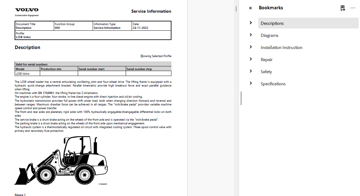
The Volvo L25B Compact Wheel Loader Service Repair Manual is a 571-page PDF workshop publication covering the mechanical, hydraulic, electrical, and structural systems of the Volvo L25B compact wheel loader.
The manual is organized around practical workshop needs: identifying how a system operates, locating its components, investigating faults, performing repairs, and checking technical specifications.
A particularly important part of the documentation concerns the hydrostatic travel drive. It contains dedicated instructions for checking and adjusting the hydrostatic pump charge pressure, cut-off valve, mechanical zero position, and starting hydraulic pump control.
These procedures are especially relevant when diagnosing hydrostatic travel problems, incorrect drive response, or pump control adjustments.
The manual also addresses the machine's diesel engine, fuel delivery, cooling, electrical components, braking system, steering equipment, articulated frame, operator cab, and working hydraulics.
Unlike publications for larger Volvo wheel loaders, the L25B documentation includes detailed structural procedures for separating the machine at the frame joint and replacing the front and rear pivot bearings while the machine is separated.
Other notable subjects include inching and brake pedal adjustment, EGR sensor replacement, diesel heater fault diagnosis, hydraulic pressure limiting valve adjustments, and Boom Suspension System servicing.
The publication is supported by numbered wiring diagrams, hydraulic schematics, troubleshooting charts, component descriptions, installation instructions, workshop safety guidance, and technical specifications.
MANUAL INFORMATION
- Manufacturer: Volvo Construction Equipment
- Equipment Model: Volvo L25B Compact Wheel Loader
- Manual Type: Service Repair / Workshop Manual
- Total Pages: 571
- File Format: PDF
- Language: English
- Technical Information Updated: 2022
- Delivery: Digital Download
A CLOSER LOOK AT THE WORKSHOP CONTENT
The following sections describe the repair and technical information included in the manual.
1. ENGINE CONSTRUCTION AND OPERATION
The engine chapters introduce the principal mechanical components and their functions.
Engine components described:
- Engine assembly
- Camshaft
- Crankshaft
- Cylinder head
- Valve mechanism
- Lubrication system
- Oil pump
- Fuel feed pump
- Fuel system
- Cooling system
- Air filter
The documentation provides engine descriptions alongside technical specifications and repair instructions.
Engine Removal and Installation
The manual includes procedures for:
- Engine removal
- Engine installation
- Engine-related service positions
- Workshop preparation and safety
2. ENGINE MECHANICAL TESTING AND ADJUSTMENTS
The repair section provides procedures for diagnosing and servicing mechanical engine components.
Included operations:
- Cylinder compression testing
- Engine valve adjustment
- Engine idle speed checking
- Engine idle speed adjustment
- Engine belt replacement
- Fan belt replacement
- Alternator belt replacement
- Exhaust manifold gasket replacement
These procedures provide a reference for mechanical engine maintenance and fault investigation.
3. FUEL SUPPLY AND INJECTION SYSTEM
The fuel system documentation includes descriptions of fuel delivery components and their servicing.
Fuel system subjects:
- Fuel feed pump
- Fuel supply system
- Fuel filters
- Injection valve
- Fuel tank capacity
Repair procedures:
- Fuel pump removal
- Fuel pump installation
- Fuel filter replacement
- Injection valve checking
The manual also provides engine and fuel system reference specifications.
4. EXHAUST GAS RECIRCULATION AND COOLING
The repair instructions include a specific procedure for EGR (Exhaust Gas Recirculation) sensor replacement.
Additional engine support system repairs include:
- Radiator removal
- Radiator installation
- Thermostat replacement
- Cooling system descriptions
This section supports work on the engine's cooling and related components.
5. HYDROSTATIC POWER TRANSMISSION
The power transmission section is one of the main technical features of the Volvo L25B manual.
Hydrostatic Drive Components
The descriptions cover:
- Hydrostatic pump
- Travel motor
- Hydraulic pump coupling
- Drive axles
- Power transmission operation
The manual includes troubleshooting information for identifying and correcting power transmission faults.
Hydrostatic Drive Troubleshooting
Included diagnostic references:
- Power transmission troubleshooting chart
- Troubleshooting and corrective actions
- Hydrostatic drive component descriptions
- Hydrostatic pump testing procedures
6. HYDROSTATIC PUMP CHARGE PRESSURE
The manual contains a dedicated procedure for:
Hydrostatic Pump Charge Pressure – Checking and Adjusting
This information is useful when examining the pressure supply required for correct hydrostatic drive operation.
The manual also includes technical specifications and tightening torque references for the travel hydraulic pump.
7. HYDROSTATIC PUMP CUT-OFF VALVE
A separate workshop procedure covers:
Hydrostatic Pump Cut-Off Valve – Checking and Adjusting
The documentation provides the procedure required for checking and setting this hydrostatic pump control component.
8. HYDROSTATIC PUMP MECHANICAL ZERO POSITION
One of the most distinctive repair subjects in this publication is:
Hydrostatic Pump Mechanical Zero Position – Checking and Adjusting
This procedure is relevant to the hydrostatic transmission's neutral setting and should be performed according to the manual's specified service instructions.
9. HYDROSTATIC DRIVE PUMP AND MOTOR REPAIRS
The manual includes:
- Hydraulic pump replacement
- Hydraulic motor replacement
- Start hydraulic pump control checking
- Start hydraulic pump control adjustment
- Output shaft induction sensor replacement
The output shaft induction sensor appears in more than one repair reference in the table of contents.
10. DRIVE AXLES
The drivetrain documentation covers axle construction and removal procedures.
Included subjects:
- Drive axle descriptions
- Axle removal
- Axle installation
- Front axle specifications
- Rear axle specifications
- Front axle capacity
- Rear axle capacity
- Axle tightening torques
- Front and rear axle weights
11. BRAKE SYSTEM DESIGN AND OPERATION
The manual explains the braking system and provides a dedicated troubleshooting section.
Brake documentation includes:
- Brake system design
- Brake system operation
- Brake troubleshooting
- Corrective actions for brake faults
Brake Repair Procedures
- Brake cylinder replacement
- Brake pad replacement
- Brake system bleeding
- Inching and brake pedal adjustment
12. INCHING AND BRAKE PEDAL ADJUSTMENT
The inching and brake pedal adjustment procedure is an important part of the L25B workshop documentation.
It provides a technical reference for servicing the pedal arrangement associated with machine travel and braking control.
13. HYDRAULIC STEERING SYSTEM
The steering section describes the machine's steering equipment and provides troubleshooting instructions.
Included subjects:
- Steering system operation
- Steering valve
- Steering hydraulic pressure
- Steering troubleshooting
- Steering specifications
Steering Repairs
- Steering valve removal
- Steering valve installation
- Steering working pressure checking
- Steering working pressure adjustment
14. ARTICULATED FRAME CONSTRUCTION
The frame section explains the structure of the compact wheel loader and its articulated joint.
Documented subjects:
- Frame design
- Frame joint
- Front pivot bearing
- Rear pivot bearing
- Steering joint
- Frame weights
- Steering joint tightening torques
15. SEPARATING THE MACHINE AT THE FRAME JOINT
The manual contains a dedicated procedure for:
Frame Joint – Separating Machine
This procedure is especially relevant when major articulation joint repairs require the front and rear machine sections to be separated.
Reassembly
The documentation also includes:
Frame Joint – Assembly of Separated Machine
These procedures should be followed with the appropriate lifting, supporting, and safety equipment.
16. FRONT AND REAR PIVOT BEARING REPLACEMENT
The manual contains separate repair procedures for:
- Front pivot bearing replacement with machine separated
- Rear pivot bearing replacement with machine separated
This is an important feature for workshops servicing articulation joint wear or damage.
17. ELECTRICAL SYSTEM COMPONENTS
The electrical chapters describe the machine's basic electrical architecture and components.
Included information:
- Electrical system description
- Engine-side electrical components
- Instrument panel
- Alternator
- Starter motor
- Battery
- Air preheating
- Relays
- Fuses
- Electrical distribution box
- Connectors
- Cable markings
- Lighting circuits
18. ELECTRICAL REPAIR PROCEDURES
The manual includes:
- Alternator removal
- Alternator installation
- Starter motor replacement
- Battery charging
- Electrical system work instructions
Electrical Component Identification
The documentation provides:
- Engine compartment relay and fuse locations
- Electrical distribution box relay and fuse information
- Connector overview
- Instrument panel electrical circuit
- Lighting equipment overview
- Cable marking explanations
19. ELECTRICAL WIRING DIAGRAMS
The publication includes 19 numbered electrical wiring diagrams.
Wiring diagram references:
- Wiring diagram 1
- Wiring diagram 2
- Wiring diagram 3
- Wiring diagram 4
- Wiring diagram 5
- Wiring diagram 6
- Wiring diagram 7
- Wiring diagram 8
- Wiring diagram 9
- Wiring diagram 10
- Wiring diagram 11
- Wiring diagram 12
- Wiring diagram 13
- Wiring diagram 14
- Wiring diagram 15
- Wiring diagram 16
- Wiring diagram 17
- Wiring diagram 18
- Wiring diagram 19
The electrical section also includes wiring diagram figure explanations.
20. CAB AND OPERATOR COMPARTMENT
The cab documentation includes descriptions, repair references, and component information.
Included subjects:
- Cab mounting
- Cab mounting tightening torques
- Windows
- Interior and exterior plastic components
- Diesel heater
- Operator compartment equipment
21. DIESEL HEATER OPERATION AND FAULT DIAGNOSIS
The manual contains a separate technical section for the diesel heater.
Included information:
- Diesel heater description
- Diesel heater operating principles
- Fault mode diagnosis
- Symptom-based malfunction diagnosis
- Error code troubleshooting
- Combination sensor checking
This section is particularly useful for investigating heater-related faults in applicable machine configurations.
22. CAB WINDOWS AND PLASTIC COMPONENT REPAIRS
The publication includes:
- Windscreen replacement
- Rear window replacement
- Cab component disassembly and assembly
- Repair of minor plastic component damage
The plastic repair documentation addresses scratches, dents, and breaks in interior and exterior plastic parts.
23. WORKING HYDRAULIC SYSTEM
The hydraulic section describes the main components used to operate the loader equipment.
Included components:
- Hydraulic pumps
- Hydraulic oil tank
- Main control valve
- Lift cylinders
- Tilt cylinders
- Attachment locking cylinder
- Hydraulic attachment bracket
- Boom Suspension System
The documentation includes component location information and troubleshooting charts.
24. HYDRAULIC PUMPS AND CONTROL VALVES
The manual provides descriptions of the hydraulic pumps and main control valve.
Included information:
- Hydraulic pump descriptions
- Main control valve description
- Hydraulic system operation
- Hydraulic component locations
- Hydraulic troubleshooting
Hydraulic Component Repair Guidance
The manual also includes information about:
- Repairing hydraulic components in a workshop
- Storing and transporting hydraulic components
- Hydraulic oil storage and handling
- Hydraulic system cleanliness
- General hydraulic repair precautions
25. HYDRAULIC PRESSURE LIMITING VALVES
The repair section includes procedures for checking and adjusting hydraulic pressure limiting valves.
Documented procedures:
- Primary pressure limiting valve checking
- Primary pressure limiting valve adjustment
- Secondary pressure limiting valve checking
- Secondary pressure limiting valve adjustment
The table of contents identifies two secondary pressure limiting valve procedure references.
26. LIFTING AND TILTING HYDRAULIC CYLINDERS
The working equipment documentation contains descriptions and repair procedures for the main hydraulic cylinders.
Included operations:
- Lift cylinder replacement
- Tilt cylinder replacement
- Implement attachment hydraulic cylinder replacement
The descriptions also cover the lifting and tilting cylinder arrangements.
27. HYDRAULIC QUICKFIT ATTACHMENT BRACKET
The manual includes a description of the hydraulic attachment bracket (Quickfit).
This section provides technical information about the hydraulic attachment locking arrangement.
The repair procedures include replacement of the implement attachment hydraulic cylinder.
28. BOOM SUSPENSION SYSTEM
The manual describes the Boom Suspension System and provides hydraulic diagrams for its operation.
Included subjects:
- Boom Suspension System description
- Boom Suspension System hydraulic circuit
- Boom Suspension System installation instructions
29. HYDRAULIC DIAGRAMS
The hydraulic diagram collection includes:
- Working hydraulics diagram
- Additional working hydraulics diagram version
- Boom Suspension System hydraulic diagram
- Control valve hydraulic diagram
These drawings support component identification and hydraulic circuit troubleshooting.
30. OPTIONAL EQUIPMENT INSTALLATION
The manual contains installation instructions for selected equipment.
Included installation subjects:
- Boom Suspension System
- CareTrack
- CareTrack 2
- Hydraulic pump 45 L/min
These instructions apply to the equipment configurations identified in the documentation.
31. WORKSHOP SERVICE POSITIONS AND SPECIAL TOOLS
The repair section includes references to workshop service positions and special equipment.
Listed special tools:
- E-tool cab support
- E-tool guide bolts
- E-tool sleeve
The documentation also includes service positions and operation numbers for additional work.
32. WORKSHOP SAFETY
The safety section provides instructions and precautions for working on the machine.
Included subjects:
- General service safety
- Loader boom safety strut
- Working under a raised boom
- Hydraulic system safety
- Hydraulic accumulator handling
- Battery handling
- Refrigerant safety
- Oil and fuel handling
- Tyre handling
- Fire prevention
- Inspection following fire or heat exposure
- Decontamination
- Hazardous fluid handling
- Waste disposal
- Working in environmentally contaminated areas
- Safe machine service positions
- Starting with booster batteries
33. TECHNICAL SPECIFICATIONS
The publication contains specifications, fluid capacities, component weights, and tightening torque references.
| System | Technical Information |
|---|---|
| Engine | Specifications, component weights |
| Fuel system | Fuel tank capacity |
| Air filtration | Air filter technical data |
| Electrical | Electrical system specifications |
| Power transmission | Hydrostatic drive and transmission specifications |
| Hydrostatic pump | Tightening torque specifications |
| Drive axles | Front and rear axle capacities and weights |
| Brakes | Brake specifications and tightening torques |
| Steering | Steering unit specifications and tightening torques |
| Frame | Frame design, frame weights, steering joint tightening torques |
| Wheels | Wheel tightening torques |
| Hydraulic system | Capacities and system specifications |
| Working hydraulics | Tightening torque specifications |
| Air conditioning | Capacity information |
| Diesel heater | Diesel heater specifications |
WHEN CAN THIS MANUAL BE USEFUL?
The Volvo L25B workshop manual can assist with:
- Engine compression testing
- Fuel pump removal and installation
- Engine valve adjustment
- EGR sensor replacement
- Hydrostatic pump charge pressure testing
- Hydrostatic pump cut-off valve adjustment
- Hydrostatic pump mechanical zero adjustment
- Hydraulic travel motor replacement
- Inching and brake pedal adjustment
- Brake system bleeding
- Steering pressure adjustment
- Frame separation and reassembly
- Front and rear pivot bearing replacement
- Electrical wiring troubleshooting
- Diesel heater fault diagnosis
- Hydraulic pressure limiting valve adjustment
- Lift and tilt cylinder replacement
- Quickfit attachment hydraulic servicing
WHO IS THIS MANUAL FOR?
This publication is intended for:
- Compact construction equipment mechanics
- Volvo wheel loader repair workshops
- Hydrostatic drive repair technicians
- Hydraulic system specialists
- Equipment fleet maintenance teams
- Experienced Volvo L25B owners
MACHINE COMPATIBILITY
This manual is identified for the Volvo L25B Compact Wheel Loader.
Before purchasing, verify the machine model, serial number, engine configuration, hydrostatic drive arrangement, and installed optional equipment.
Some procedures and diagrams may apply only to specific configurations.
Technical Information Updated: 2022 refers to the documentation update year and does not necessarily indicate the year of manufacture of the machine.
DIGITAL PDF DOCUMENTATION
This product contains 571 pages of service and repair documentation in PDF format.
The manual includes component descriptions, troubleshooting charts, repair procedures, electrical wiring diagrams, hydraulic schematics, installation instructions, safety guidance, and technical specifications.
Digital product only. No printed manual or physical item will be shipped.
A compatible PDF reader is required to view the document.
IMPORTANT DOWNLOAD INFORMATION
Due to the large file size, this manual is delivered via a Dropbox download link to ensure a smooth downloading experience without overloading our website. No software installation, Dropbox account, or login is required to access and download your manual. Simply open the provided link and download the file directly to your device. If you experience any issues accessing or downloading your manual, please don't hesitate to contact us. We're always happy to help and will assist you as quickly as possible!
EXPLORE MORE VOLVO SERVICE MANUALS
BROWSE VOLVO WHEEL LOADER MANUALS
VIEW ALL VOLVO EQUIPMENT MANUALS
EXPLORE THE COMPLETE MANUAL COLLECTION
Detailed contents:
Descriptions
(0) GENERAL
Conversion tables
Description
(1) STANDARD PARTS, SERVICE
Towing a disabled machine
Electric welding
Charging batteries
Cleanliness, braking and hydraulic system
Work on the machine’s electrical system
Maintenance service, general
Recommended lubricants
(2) ENGINE WITH MOUNTING AND EQUIPMENT
Air filter, description
Camshaft, description
Cooling system, description
Crankshaft, description
Cylinder head, description
Engine, description
Engine, installing
Engine, removing
Fuel feed pump, description
Fuel system, description
Lubrication system, description
Oil pump, description
Valve mechanism, description
(3) ELEC. SYSTEM; WARNING SYSTEM; INFORMATION SYSTEM; INSTRUMENTS
Instrument panel, description
Electrical components, engine side, description
Relays and fuses in engine compartment
Relays and fuses in electrical distribution box
Wiring diagram, figure text
Cable markings
Instrument panel, electrical circuit
Connectors, overview.
Overview lighting, devices
Air preheating, description
Battery, charging
Battery, description
Electrical system, description
Electrical system, instructions
(4) POWER TRANSMISSION
Drive axles, description
Hydraulic pump coupling, description
Hydrostatic pump, description
Power transmission, description
Travel motor, description
Troubleshooting and actions to fix problems
Troubleshooting chart
(5) BRAKE
Brake design
Description brake system
Troubleshooting and actions to fix problems
(6) STEERING
Steering system, description
Troubleshooting and actions to fix problems
(7) FRAME;SPRINGS;DAMPING;AXLE SUSPENSION; WHEEL TRACK UNIT
Frame joint, assembly of separated machine
Frame joint, Replacing the front pivot bearing with machine separated
Frame joint, replacing the rear pivot bearing with machine separated
Frame joint, separating machine
Frame, description
(8) MACHINERY HOUSE;CAB;EXTERIOR TRIM PARTS ANYWHERE
Cab mounts, tightening torques
Diesel heater, description
Diesel heater, principles
Fault mode diagnosis
Repairs of minor damage on internal and external plastic parts (scratches, dents, breaks)
Symptom malfunction
Windows, general
(9) HYDRAULIC SYSTEM;DIGGING HANDLING GRADING EQUIPM.; MISC. EQUIP
Working hydraulic system, component location 2
Tilting and lifting cylinders 2
Tilting and lifting cylinders
Lock cylinder
Hydraulic attachment bracket (quickfit), description
Boom Suspension System, description
Hydraulic pumps, description
Main control valve, description
Hydraulic oil tank, description
Working hydraulic system, component location
Hydraulic system, description
Troubleshooting chart
Hydraulic components, storing and transporting
Hydraulic system, repair of hydraulic components in workshop
Hydraulic oil, storage and handling
Cleanliness when working on hydraulic components
General information to note when working on the hydraulic system
Diagrams
(3) ELEC. SYSTEM; WARNING SYSTEM; INFORMATION SYSTEM; INSTRUMENTS
Wiring diagram 1
Wiring diagram 2
Wiring diagram 3
Wiring diagram 4
Wiring diagram 5
Wiring diagram 6
Wiring diagram 7
Wiring diagram 8
Wiring diagram 9
Wiring diagram 10
Wiring diagram 11
Wiring diagram 12
Wiring diagram 13
Wiring diagram 14
Wiring diagram 15
Wiring diagram 16
Wiring diagram 17
Wiring diagram 18
Wiring diagram 19
(4) POWER TRANSMISSION
(6) STEERING
(8) MACHINERY HOUSE;CAB;EXTERIOR TRIM PARTS ANYWHERE
(9) HYDRAULIC SYSTEM;DIGGING HANDLING GRADING EQUIPM.; MISC. EQUIP
Hydraulic diagram working hydraulics (2)
Hydraulic diagram working hydraulics
Hydraulic diagram, Boom Suspension System
Hydraulic diagram, control valve
Installation Instruction
Boom Suspension System
CareTrack 2
CareTrack
Hydraulic pump 45Lmin
Read and understand
Table of contents
Repair
(0) GENERAL
E-tool Cab support
E-tool Guide bolts
E-tool Sleeve
Operation numbers for additional work
Service positions
(2) ENGINE WITH MOUNTING AND EQUIPMENT
Belt, changing
Cylinder compression, testing
EGR (exhaust gas recirculation) sensor, replacing
Exhaust manifold gasket, replacing
Fan belt and or alternator belt, replacing
Fuel filters, replacing
Fuel pump, installing
Fuel pump, removing
Idling speed, checking and adjusting
Injection valve, check
Radiator, installing
Radiator, removing
Thermostat, replacing
Valves, adjusting
(3) ELEC. SYSTEM; WARNING SYSTEM; INFORMATION SYSTEM; INSTRUMENTS
Alternator, installing
Alternator, removing
Starter motor, replacing
(4) POWER TRANSMISSION
Axle, installing
Axle, removing
Hydraulic motor, replacing
Hydraulic pump, replacing
Hydrostatic pump charge pressure, checking and adjusting
Hydrostatic pump cut off valve, checking and adjusting
Hydrostatic pump mechanical zero position, checking and adjusting
Induction sensor for output shaft, replacing
Induction sensor for output shaft, replacing2
Start hydraulic pump control, checking and adjusting
(5) BRAKE
Brake cylinder, replacing
Brake pads, replacing
Brake system, bleeding
Inching and brake pedal, adjusting
(6) STEERING
Steering system working pressure, checking and adjusting
Steering valve, installing
Steering valve, removing
(8) MACHINERY HOUSE;CAB;EXTERIOR TRIM PARTS ANYWHERE
Combination sensor, check
Disassembly and assembly
Error code, troubleshooting
Rear window, replacing
Windscreen, replacing
(9) HYDRAULIC SYSTEM;DIGGING HANDLING GRADING EQUIPM.; MISC. EQUIP
Implemental attachment hydraulic cylinder, replacing
Lift cylinder, replacing
Primary pressure limiting valve, checking and adjusting
Secondary pressure limiting valve, checking and adjusting
Secondary pressure limiting valve, checking and adjusting2
Tilt cylinder, replacing
Vacuum pump, connection
Safety
(1) STANDARD PARTS, SERVICE
CE-marking, EMC-directive
Checklist after a fire or heat exposure
Decontamination
Environmental handling for the future
Environmentally hazardous fluids
Environmentally safe handling
Fire prevention measures
Health hazards with paint, plastics and rubber
Loader boom, safety strut
Safety concerns everybody!
Safety rules when servicing
Safety when handling accumulators
Safety when handling oils and fuel
Safety when handling the machine
Safety when working on hydraulic systems
Safety when working with batteries
Safety when working with refrigerant
Service position 1 (2)
Service position 1 (3)
Service position 1 (4)
Service position 1 (5)
Service position 1
Service position 2 (2)
Service position 2 (3)
Service position 2 (4)
Service position 2 (5)
Service position 2
Some simple rules regarding tyre handling
Starting with booster batteries
Waste handling
Working in environmentally contaminated areas
Working under raised boom
Specifications
(0) GENERAL
Air conditioning, capacity 1
Air conditioning, capacity
Axles and propeller shaft, tightening torque
Axles, specifications
Brake, specifications
Brakes, tightening torques
Damper weight, weight
Electrical system, specifications
Front axle, capacities
Front axle, weight
Hydraulic system, capacities
Hydraulic system, specification
Power transmission, specifications
Rear axle, capacity
Rear axle, weight
Steering unit, specification
Steering, tightening torques 1
Steering, tightening torques
Transporting the machine
Travel hydraulics hydrostatic pump, tightening torque
Volvo standard tightening torques
Working hydraulics, tightening torques
(1) STANDARD PARTS, SERVICE
(2) ENGINE WITH MOUNTING AND EQUIPMENT
Air filter, technical data
Engine, specifications 1
Engine, specifications
Engine, weights
Fuel tank, capacities
(3) ELEC. SYSTEM; WARNING SYSTEM; INFORMATION SYSTEM; INSTRUMENTS
(4) POWER TRANSMISSION
(6) STEERING
(7) FRAME; SPRINGS; DAMPING; AXLE SUSPENSION; WHEEL, TRACK UNIT
Hydraulic system, capacities
Wheels, tightening torques
Steering joint, tightening torques
Damper weight, weight
Frame L25B, weights
Frame, design
(8) MACHINERY HOUSE; CAB; EXTERIOR TRIM PARTS ANYWHERE
Air conditioning, capacity
Diesel heater, specifications
More products