$14.80
VOLVO L330C LL BM WHEEL LOADER SERVICE REPAIR MANUAL PDF – 861 PAGES
Detailed Workshop Documentation for Engine, Contronic System, APS II Transmission, Steering and Hydraulic Repairs
The Volvo L330C LL BM Wheel Loader Service Repair Manual is an extensive 861-page technical publication covering maintenance, troubleshooting, inspection, adjustment, component replacement, and workshop repair procedures for the Volvo L330C LL BM wheel loader.
With technical information updated in 2020, this digital PDF manual brings together system descriptions, electrical wiring diagrams, hydraulic schematics, repair procedures, installation instructions, workshop safety information, and technical specifications.
The documentation provides detailed coverage of the Volvo Contronic monitoring system, engine injection timing, APS II automatic power shift transmission, torque converter, ORBITROL steering valve, Flow Amplifier, Comfort Drive Control (CDC), and Boom Suspension System (BSS).
A particularly valuable feature is the inclusion of procedures for replacing transmission clutch discs and clutch drum bearings directly in the machine, along with hydraulic pump balancing, load-sensing pressure checks, brake accumulator servicing, and lift and tilt cylinder repairs.
The manual also includes an extensive collection of electrical wiring diagrams and technical references for servicing the machine's mechanical, electrical, transmission, braking, steering, and hydraulic systems.
It is a practical reference for professional heavy equipment repair workshops, fleet maintenance departments, and experienced Volvo wheel loader owners.
MANUAL INFORMATION
- Manufacturer: Volvo Construction Equipment
- Equipment Model: Volvo L330C LL BM Wheel Loader
- Manual Type: Service Repair / Workshop Manual
- Format: PDF
- Total Pages: 861
- Technical Information Updated: 2020
- Delivery: Digital Download
- Language: English
WHAT DOES THIS VOLVO L330C LL BM MANUAL COVER?
The publication contains the following principal categories:
- General Descriptions
- Electrical and Hydraulic Diagrams
- Installation Instructions
- Workshop Repair Procedures
- Safety Information
- Technical Specifications
These sections provide technical coverage of the engine, electronic monitoring, transmission, axles, brakes, steering, frame, operator cab, working hydraulics, and optional equipment.
1. GENERAL SERVICE AND WORKSHOP INFORMATION
The manual includes essential service instructions and technical references for maintaining the machine.
Included topics:
- General machine descriptions
- Electrical welding precautions
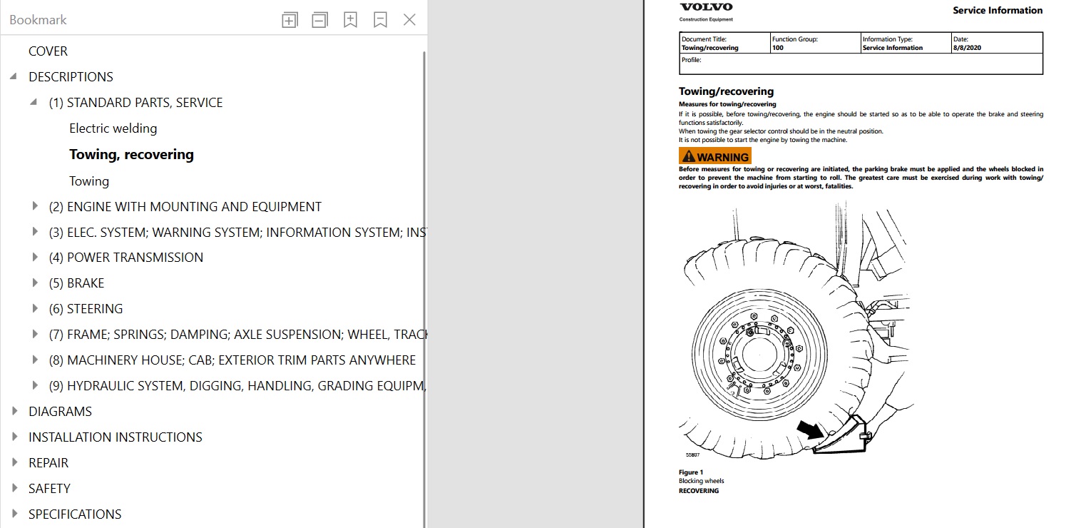
- Machine towing
- Machine recovery procedures
- Product identification plates
- Workshop operation time guide
- Workshop-made special tool drawings
- General technical specifications
- Standard tightening torques
- Volvo BM standard tightening torques
2. ENGINE MECHANICAL COMPONENTS
The engine section includes descriptions, technical specifications, and workshop repair procedures for major engine components.
ENGINE COMPONENTS
- Cylinder block
- Cylinder head
- Cylinder liners
- Pistons
- Camshaft
- Engine timing gears
- Injection timing device
- Engine lubrication system
- Engine cooling system
- Oil cooler
- Cylinder head, cylinder block and cylinder liner sealing arrangements
ENGINE REPAIR PROCEDURES
- Engine removal
- Engine installation
- Engine functional checking
- Engine idle speed checking
- Engine idle speed adjustment
- Engine stall speed checking
- Oil sump gasket replacement
- Electrical key-turn engine stop checking
- Electrical key-turn engine stop adjustment
3. FUEL INJECTION SYSTEM AND INJECTION TIMING
The manual includes technical information and procedures for checking and adjusting fuel injection timing.
FUEL SYSTEM COMPONENTS
- Injection pump
- Injection timing device
- Fuel injectors
- Fuel tank
- Stop solenoid
- Fuel supply system
FUEL SYSTEM REPAIR PROCEDURES
- Injection angle checking
- Injection angle adjustment
- Injection timing device checking
- Fuel system air bleeding
- Fuel tank replacement
- Engine idle speed checking and adjustment
- Engine stall speed checking
These procedures are particularly useful when servicing the fuel injection system and checking engine operating performance.
4. ENGINE COOLING AND HYDRAULIC FAN SYSTEM
The cooling system section contains descriptions, specifications, and pressure adjustment procedures.
COOLING SYSTEM COMPONENTS
- Engine cooling system
- Charge-air cooler (intercooler)
- Coolant filter
- Cooling fan
- Hydraulic fan pump and motor
- Engine cooling components
COOLING SYSTEM SERVICE PROCEDURES
- Cooling fan hydraulic pressure checking
- Cooling fan hydraulic pressure adjustment
- Cooling system functional descriptions
- Cooling system technical specifications
5. ENGINE LUBRICATION AND OIL COOLING
The manual includes information about the engine lubrication system and related components.
Included topics:
- Engine lubrication system
- Oil cooler
- Engine lubrication specifications
- Engine mechanical component references
- Engine service and tightening torque specifications
6. CONTRONIC ELECTRONIC MONITORING SYSTEM
An important feature of this publication is its coverage of the Volvo Contronic System.
CONTRONIC SYSTEM INFORMATION
- Contronic system description
- Electronic monitoring functions
- Service Contronic Display Unit
- Instrumentation
- Warning functions
- Functions outside the central warning system
- Electrical control unit connections
- Units connected to the control unit
- Operation with the ECU disconnected
ELECTRICAL SYSTEM COMPONENTS
- Electrical distribution box
- Cab electrical distribution box
- Control unit
- Relays
- Diodes
- Electrical connectors
- Instruments and controls
7. ELECTRICAL SYSTEM TROUBLESHOOTING AND SERVICE
The electrical section includes service instructions and circuit identification information.
Included topics:
- Battery charging
- Electrical system servicing precautions
- Electrical distribution boxes
- Electrical control unit functions
- Relay functions
- Connector identification
- Diode identification
- Circuit identification
- Wiring diagram explanations
- Electrical troubleshooting references
8. APS II AUTOMATIC POWER SHIFT TRANSMISSION
The power transmission section contains detailed information about the APS II transmission and its operating functions.
TRANSMISSION SYSTEMS
- APS II Automatic Power Shift with Mode Selector
- Hydraulic transmission
- Torque converter
- Gear shifting control valve
- Gear selector signals
- ECU gearshift control
- Dual-control forward and reverse shifting
- Trimmer valve block
- Transmission hydraulic circuits
TRANSMISSION MONITORING
- Transmission oil pressure
- Transmission filter monitoring
- Brake cooling circuit filter monitoring
- Gear shifting signals
- Electronic transmission control functions
9. TRANSMISSION CLUTCH DISC AND BEARING REPAIRS
The manual contains detailed procedures for servicing transmission clutch components directly in the machine.
CLUTCH DISC REPLACEMENT
- First-gear clutch disc replacement in the machine
- Second-gear clutch disc replacement in the machine
- Forward clutch disc replacement in the machine
- Reverse clutch disc replacement in the machine
- Third-gear clutch disc replacement in the machine
- Fourth-gear clutch disc replacement in the machine
CLUTCH DRUM BEARING REPLACEMENT
- First-gear clutch drum bearing replacement in the machine
- Second-gear clutch drum bearing replacement in the machine
- Forward clutch drum bearing replacement in the machine
- Reverse clutch drum bearing replacement in the machine
- Third-gear clutch drum bearing replacement in the machine
- Fourth-gear clutch drum bearing replacement in the machine
These procedures make the manual especially relevant for workshops servicing the internal components of the APS II transmission.
10. TORQUE CONVERTER AND TRANSMISSION REPAIRS
The publication includes additional drivetrain repair procedures.
Included operations:
- Torque converter replacement
- Transmission removal
- Transmission installation
- Transmission oil pressure checking
- Transmission hydraulic diagram
- Torque converter and transmission functional descriptions
- Transmission technical specifications
11. DRIVE AXLES, DIFFERENTIALS AND HUB REDUCTIONS
The manual contains descriptions and repair procedures for drivetrain components.
AXLE AND DIFFERENTIAL SYSTEMS
- Front and rear axles
- Differential
- Limited Slip differential
- Differential carrier assembly
- Hub reduction gears
- Propeller shafts
DRIVETRAIN REPAIR PROCEDURES
- Differential carrier removal
- Differential carrier installation
- Hub reduction gear seal replacement
- Hub reduction gear reconditioning
- Rear axle removal
- Rear axle installation
- Propeller shaft removal
- Support bearing reconditioning
12. BRAKING SYSTEM
The braking section provides technical descriptions and workshop procedures for the service brakes and parking brake.
BRAKE SYSTEM COMPONENTS
- Hydraulic brake system
- Brake accumulators
- Brake pump
- Brake discs
- Parking brake
- Brake cooling circuit
BRAKE REPAIR PROCEDURES
- Brake disc replacement
- Brake disc wear checking
- Brake accumulator seal replacement
- Brake accumulator checking
- Brake accumulator adjustment
- Brake accumulator precharge pressure checking
- Brake pump replacement
- Brake circuit pressure checking
- Brake circuit pressure adjustment
- Brake system pressure checking
- Brake system pressure adjustment
- Brake retardation functional checking
- Parking brake adjustment
- Manual parking brake release
13. STEERING SYSTEM AND FLOW AMPLIFIER
The steering section includes descriptions and procedures for the machine's hydraulic steering components.
STEERING COMPONENTS
- ORBITROL steering valve
- Flow Amplifier
- Steering control valve
- Steering cylinders
- Hydraulic steering pumps
- Steering hydraulic system
STEERING REPAIR PROCEDURES
- Flow Amplifier reconditioning
- Steering valve reconditioning
- Steering cylinder replacement
- Steering working pressure checking
- Steering working pressure adjustment
14. COMFORT DRIVE CONTROL (CDC)
The manual includes technical information for the lever steering system.
Included topics:
- CDC lever steering description
- Lever steering hydraulic system
- Lever steering functions
- Steering lever and CU20 ramp generator
- CU20 input/output voltage checking
- Lever steering speed adjustment
15. FRAME, AXLE SUSPENSION AND WHEELS
The frame section provides descriptions and repair procedures for structural components.
FRAME AND SUSPENSION COMPONENTS
- Machine frame
- Frame joint
- Axle suspension
- Wheels and hubs
- Counterweights
FRAME AND SUSPENSION REPAIRS
- Axle suspension axial clearance measurement
- Axle suspension radial clearance measurement
- Axle suspension bushing replacement
- Axle suspension seal replacement
- Axle suspension axial clearance adjustment
- Wheel removal
- Wheel installation
- Extra counterweight removal
- Extra counterweight installation
16. OPERATOR CAB AND AIR CONDITIONING
The cab section contains descriptions and service procedures for the operator environment.
Included topics:
- Cab general descriptions
- Cab electrical system
- Air conditioning performance testing
- Roll-over bar removal
- Roll-over bar installation
- Cab-related technical specifications
17. WORKING HYDRAULIC SYSTEM
The hydraulic section includes detailed descriptions, repair procedures, and technical specifications for the loader's working hydraulic equipment.
HYDRAULIC COMPONENTS
- Hydraulic oil tank
- Hydraulic pumps
- Hydraulic control valves
- Servo system
- Lift cylinders
- Tilt cylinders
- Lift frame
- Tilting arm
- Tilting links
- Hydraulic attachment locking
HYDRAULIC SYSTEM INFORMATION
- Working hydraulic system descriptions
- Hydraulic circuit diagrams
- Hydraulic control valve functions
- Shock and anti-cavitation functions
- Hydraulic system leakage testing
- Hydraulic system checking procedures
18. HYDRAULIC PUMPS P1, P2, P3 AND P4
A distinctive feature of this manual is its detailed coverage of the four hydraulic pumps and their balancing procedures.
HYDRAULIC PUMP SERVICE
- Hydraulic pump replacement
- Hydraulic pump repair
- Hydraulic pump balancing
- Hydraulic pump maximum pressure adjustment
- Hydraulic pump P1–P4 balance checking
- Load-sensing signal checking for pumps P1–P4
- Hydraulic system checking procedures
- Standby pressure checking
- Standby pressure adjustment
HYDRAULIC PRESSURE AND VALVE TESTING
- Pressure-reducing valves R1 and R2 closing pressure checking
- Safety valve TB opening pressure checking
- Back-up valve opening pressure checking
- Hydraulic system leakage testing
19. SERVO SYSTEM AND CONTROL VALVES
The manual includes procedures for checking and adjusting hydraulic servo functions.
Included operations:
- Servo system descriptions
- Servo pressure checking
- Servo pressure adjustment
- Servo pressure checking at the control valve spool
- Servo valve operating control adjustment
- Hydraulic control valve functions
- Hydraulic system checking procedures
20. LIFTING CYLINDERS AND LIFT FRAME
The manual contains procedures for servicing the loader's lifting equipment.
LIFT CYLINDER REPAIRS
- Lift cylinder replacement
- Lift cylinder seal replacement in the machine
- Lift cylinder front bushing replacement
- Lift cylinder rear bushing replacement
LIFT FRAME SERVICE
- Lift frame descriptions
- Lift frame-related component references
- Boom kick-out adjustment
- Boom kick-out function descriptions
21. TILTING CYLINDERS AND LINKAGE
The tilting equipment section includes repair procedures for cylinders, bearings, and linkage components.
TILT CYLINDER REPAIRS
- Tilt cylinder replacement
- Tilt cylinder seal replacement in the machine
- Tilt cylinder front bushing replacement
- Tilt cylinder rear bushing replacement
TILTING LINKAGE REPAIRS
- Tilting arm bearing replacement
- Tilting link replacement
- Tilting link bearing replacement
22. BOOM KICK-OUT AND BUCKET POSITIONER
The manual includes information about the automatic positioning functions used in loader operation.
Included topics:
- Boom kick-out function
- Boom kick-out adjustment
- Bucket positioner function
- Bucket positioner adjustment
- Lifting detent function
- Floating position
- Floating position detent function
23. BOOM SUSPENSION SYSTEM (BSS)
The manual provides technical information and repair procedures for the Boom Suspension System.
Included topics:
- Boom Suspension System description
- BSS functional checking
- Hydraulic accumulator checking
- Hydraulic accumulator adjustment
- Hydraulic accumulator seal replacement
24. THIRD AND FOURTH HYDRAULIC FUNCTIONS
The manual includes descriptions and pressure adjustment procedures for auxiliary hydraulic functions.
Included topics:
- Third hydraulic function
- Fourth hydraulic function
- Auxiliary hydraulic pressure checking
- Auxiliary hydraulic pressure adjustment
- Shock pressure checking
- Shock pressure adjustment
- Separate hydraulic attachment locking
25. ELECTRICAL WIRING DIAGRAMS
The manual contains an extensive collection of electrical wiring diagrams.
INCLUDED WIRING DIAGRAM GROUPS
- Wiring diagrams 11–110
- Wiring diagrams 21–29
- Wiring diagrams 31–310
- Wiring diagrams 41–410
- Wiring diagrams 51–510
- Wiring diagrams 61–610
- Wiring diagrams 71–710
- Wiring diagrams 81–89
- Wiring diagrams 91–910
- Wiring diagrams 101–108
- Wiring diagrams 111–118
- Wiring diagrams 121–1210
- Wiring diagrams 131–1310
- Wiring diagrams 141–1410
- Wiring diagrams 151–157
- Wiring diagrams 161–165
- Wiring diagrams 171–177
- Wiring diagrams 181–188
- Wiring diagrams 191–1910
- Wiring diagrams 201–207
- Wiring diagrams 211–219
ADDITIONAL ELECTRICAL REFERENCES
- Connector identification codes
- Diode identification codes
- Wiring diagram symbols
- Circuit lists
- Control unit function descriptions
- Relay function descriptions
- Wiring diagram explanations
26. HYDRAULIC CIRCUIT DIAGRAMS
The manual includes hydraulic diagrams for the machine's main hydraulic systems.
Included diagrams:
- Complete hydraulic system diagram
- Working hydraulic system diagrams
- Working hydraulics basic machine functional diagram
- Steering system hydraulic diagram
- Brake and brake cooling circuit hydraulic diagram
- Transmission hydraulic diagram
27. OPTIONAL EQUIPMENT INSTALLATION
The installation section includes:
- CareTrack installation instructions
28. WORKSHOP SAFETY INFORMATION
The manual includes workshop safety instructions for servicing heavy construction equipment.
Included topics:
- General workshop safety
- Battery handling precautions
- Battery charging
- Booster battery starting
- Tyre inflation safety
- Servicing precautions
- Fire prevention
- Hazards associated with polymer materials
- Air conditioning refrigerant safety
- Machine service position
29. TECHNICAL SPECIFICATIONS
The manual includes extensive technical reference data for the machine's major systems.
ENGINE
- Engine specifications
- Cylinder block specifications
- Fuel injection system specifications
- Engine cooling system specifications
- Charge-air cooler specifications
- Lubrication system specifications
- Engine functional checking references
ELECTRICAL SYSTEM
- Electrical system specifications
- Electrical control system references
- Electrical component specifications
TRANSMISSION AND DRIVELINE
- APS II transmission specifications
- Torque converter specifications
- Axle specifications
- Differential specifications
- Transmission-related technical data
BRAKES
- Brake system specifications
- Brake accumulator specifications
- Parking brake specifications
STEERING
- Steering system specifications
- Hydraulic steering component specifications
FRAME AND CAB
- Frame specifications
- Wheel and hub specifications
- Cab-related specifications
HYDRAULICS
- Hydraulic system specifications
- Hydraulic pump specifications
- Servo system specifications
- Working hydraulic equipment specifications
- Lift and tilt cylinder specifications
GENERAL TECHNICAL DATA
- General specifications
- Tightening torques
- Volvo BM standard tightening torques
PRACTICAL WORKSHOP APPLICATIONS
This manual can assist with operations such as:
- Checking and adjusting engine injection timing
- Servicing the fuel injection system
- Checking engine idle and stall speed
- Diagnosing Contronic monitoring functions
- Checking electrical control circuits
- Servicing APS II transmission components
- Replacing transmission clutch discs in the machine
- Replacing transmission clutch drum bearings
- Replacing the torque converter
- Reconditioning hub reduction gears
- Checking brake accumulator precharge pressure
- Replacing brake discs
- Reconditioning ORBITROL steering valves
- Servicing the Flow Amplifier
- Adjusting CDC lever steering speed
- Checking hydraulic pump balance for P1–P4
- Testing load-sensing hydraulic signals
- Adjusting servo pressure
- Replacing lift and tilt cylinder seals in the machine
- Checking Boom Suspension System operation
- Adjusting third and fourth hydraulic function pressures
- Consulting electrical and hydraulic circuit diagrams
WHO IS THIS MANUAL FOR?
This technical publication is suitable for:
- Professional Volvo wheel loader technicians
- Heavy equipment repair workshops
- Construction machinery maintenance departments
- Transmission repair specialists
- Diesel equipment mechanics
- Hydraulic system repair technicians
- Experienced Volvo L330C LL BM owners carrying out maintenance and repair work
IMPORTANT COMPATIBILITY INFORMATION
This manual is identified for the Volvo L330C LL BM Wheel Loader.
Certain repair procedures, electrical diagrams, hydraulic arrangements, and equipment descriptions may apply only to particular machine configurations.
Before purchasing, verify your machine model, serial number, and installed equipment to determine whether the relevant documentation applies to your machine.
The 2020 information update refers to the technical documentation and does not necessarily represent the machine's manufacturing year.
DIGITAL PDF DELIVERY
This product is supplied as a digital PDF workshop manual.
The publication includes:
- 861 pages of technical documentation
- Engine mechanical component descriptions
- Fuel injection timing and adjustment procedures
- Contronic electronic monitoring information
- APS II transmission descriptions and repair procedures
- Transmission clutch replacement instructions
- Torque converter and drivetrain service information
- Brake accumulator and brake disc procedures
- ORBITROL steering and Flow Amplifier documentation
- CDC lever steering information
- Hydraulic pump P1–P4 balancing procedures
- Load-sensing hydraulic pressure checks
- Lift and tilt cylinder repair instructions
- Boom Suspension System information
- Third and fourth hydraulic function procedures
- Extensive electrical wiring diagrams
- Hydraulic circuit diagrams
- CareTrack installation instructions
- Workshop safety information
- Technical specifications and tightening torques
Digital product only. No printed manual will be shipped.
A compatible PDF reader is required to view the document.
IMPORTANT DOWNLOAD INFORMATION
Due to the large file size, this manual is delivered via a Dropbox download link to ensure a smooth downloading experience without overloading our website. No software installation, Dropbox account, or login is required to access and download your manual. Simply open the provided link and download the file directly to your device. If you experience any issues accessing or downloading your manual, please don't hesitate to contact us. We're always happy to help and will assist you as quickly as possible!
RELATED VOLVO WHEEL LOADER MANUALS
Looking for additional Volvo construction equipment documentation?
BROWSE VOLVO WHEEL LOADER MANUALS
Explore other Volvo wheel loader service repair manuals and parts catalogs.
VIEW ALL VOLVO EQUIPMENT MANUALS
Find additional technical publications for Volvo construction equipment.
EXPLORE THE COMPLETE MANUAL COLLECTION
Browse available workshop manuals and parts catalogs for construction and industrial machinery.
Please verify equipment compatibility before purchasing.
Detailed contents:
COVER
DESCRIPTIONS
(1) STANDARD PARTS, SERVICE
Electric welding
Towing, recovering
Towing
(2) ENGINE WITH MOUNTING AND EQUIPMENT
Camshaft
Description (2)
Description (3)
Description
Engine timing gears
Injection timing device
Oil cooler
Pistons
(3) ELEC. SYSTEM; WARNING SYSTEM; INFORMATION SYSTEM; INSTRUMENTS
Charging batteries
Contronic System
Electrical distribution box in cab
Electrical distribution box
Functions which are not included in the central warning
General description
Instruments and controls
Monitored functions
Operating with the ECU disconnected, (electrical)
Other electrical functions
Service Contronic Display Unit
Special instructions when working on the electrical system
Units connected to the control unit
(4) POWER TRANSMISSION
Limited slip type differential
(5) BRAKE
Description (2)
Description
Hydraulic diagram, brake system, brake cooling circuit
Manual release of parking brake
(6) STEERING
Description
Lever steering, CDC (Comfort Drive Control)
Lever steering, description hydraulic system
Lever steering
Steering lever and ramp generator CU20, checking voltage inout
(7) FRAME; SPRINGS; DAMPING; AXLE SUSPENSION; WHEEL, TRACK UNIT
Frame joint
(8) MACHINERY HOUSE; CAB; EXTERIOR TRIM PARTS ANYWHERE
Description
(9) HYDRAULIC SYSTEM, DIGGING, HANDLING, GRADING EQUIPM, MISC. EQUIP
Boom kick-out and bucket positioner, adjusting
Boom kick-out and bucket positioner
Description
Detent function floating position and floating position
Detent function lifting, boom kick-out (SW 18)
Functional diagram, working hydraulics, basic machine
Hydraulic diagram, working hydraulic
Hydraulic diagram, working hydraulics
DIAGRAMS
(3) ELEC. SYSTEM; WARNING SYSTEM; INFORMATION SYSTEM; INSTRUMENTS
Code key for connectors (connected to the circuit board)
Code key for connectors (other)
Code key for diodes
Codes used in wiring diagrams
Control unit, description of function
Explanations to wiring diagrams
List of circuits
Relay, description of function
Wiring diagram, 11 — 110
Wiring diagram, 21 — 29
Wiring diagram, 31 — 310
Wiring diagram, 41 — 410
Wiring diagram, 51 — 510
Wiring diagram, 61 — 610
Wiring diagram, 71 — 710
Wiring diagram, 81 — 89
Wiring diagram, 91 — 910
Wiring diagram, 101 — 108
Wiring diagram, 111 — 118
Wiring diagram, 121 — 1210
Wiring diagram, 131 — 1310
Wiring diagram, 141 — 1410
Wiring diagram, 151 — 157
Wiring diagram, 161 — 165
Wiring diagram, 171 — 177
Wiring diagram, 181 — 188
Wiring diagram, 191 — 1910 (2)
Wiring diagram, 191 — 1910
Wiring diagram, 201 — 207
Wiring diagram, 211 — 219
(6) STEERING
Hydraulic diagram, steering system
INSTALLATION INSTRUCTIONS
CARE TRACK
REPAIR
(0) GENERAL
Description
Drawings of tools (E-tools) which can be made in your own workshop
Product Identification Plates
Time Guide
(2) ENGINE WITH MOUNTING AND EQUIPMENT
Electrical key-turn engine stop, checking and adjusting
Oil sump gasket, changing
(4) POWER TRANSMISSION
Support bearing, reconditioning
(5) BRAKE
Brake discs, changing
Brake system retardation, checking function
Pressure in circuit, checking and adjusting
System pressure, checking and adjusting
(7) FRAME; SPRINGS; DAMPING; AXLE SUSPENSION; WHEEL, TRACK UNIT
Measuring axial and radial clearance in axle suspension
Changing bushings and seals in axle suspension
Adjusting axial clearance in axle suspension
(9) HYDRAULIC SYSTEM, DIGGING, HANDLING, GRADING EQUIPM, MISC. EQUIP
Cleanliness when working on hydraulic systems
Hydraulic diagram, complete
Specifications
SAFETY
(1) STANDARD PARTS, SERVICE
A few simple rules for batteries
A few simple rules of safety
A few simple rules when inflating tyres
A few simple rules when servicing
Charging batteries
Danger in connection with polymer materials
Measures to prevent fire
Refrigerant in air-conditioning units
Safety concerns everybody!
Service position
Starting with booster batteries
SPECIFICATIONS
(0) GENERAL
Brakes
Engine
Hydraulic system
Power transmission
Specifications
Steering sysem
Tightening torques
VOLVO BM standard tightening torques
(2) ENGINE WITH MOUNTING AND EQUIPMENT
Charge-air cooler (Intercooler)
Coolant filter
Cooling system (engine)
Cooling system
Cylinder block
Description (2)
Description (3)
Description of function, cooling fan
Description
Engine, checking function
Engine, fitting
Engine, removing
Fan pumpmotor, adjusting hydraulic pressure
Fan pumpmotor, checking hydraulic pressure
Fuel system, air bleeding
Fuel tank, changing
Idling speed, checking and adjusting
Injection angle (timing), adjusting
Injection angle (timing), checking
Injection pump
Injection timing device, checking
Injectors
Lubrication system
Sealing joint (cylinder head–cylinder block–cylinder liner)
Specifications (2)
Specifications (3)
Specifications (4)
Specifications (5)
Specifications (6)
Specifications (7)
Specifications (8)
Specifications (9)
Specifications (10)
Specifications (11)
Specifications (12)
Specifications (13)
Specifications (14)
Specifications
Stall speed, checking
Stop solenoid
(3) ELEC. SYSTEM; WARNING SYSTEM; INFORMATION SYSTEM; INSTRUMENTS
Specifications (2)
Specifications (3)
Specifications (4)
Specifications (5)
Specifications (6)
Specifications
(4) POWER TRANSMISSION
APS ll (Automatic Power Shift with Mode Selector)
Axles
Clutch discs 1st–2nd, changing in machine
Clutch discs, forward-reverse or 3rd– 4th, changing in machine
Clutch drum bearings, 1st or 2nd, changing in machine
Clutch drum bearings, forward, reverse, 3rd or 4th, changing in machine
Control valve, gear shifting
Description of function, torque convertertransmission
Description
Differential carrier assembly, removing and fitting
Differential
Dual control, forward–reverse shifting
Gear shifting, signal to ECU from gear selector
Gear shifting, signal to in out from the ECU
Hub reduction gear, changing seals
Hub reduction gear, reconditioning
Hydraulic diagram, transmission
Monitoring brake cooling circuit filter and transmission filter
Rear axle, fitting
Rear axle, removing
Removing propeller shafts
Specifications (2)
Specifications (3)
Specifications (4)
Specifications (5)
Specifications (6)
Specifications (7)
Specifications (8)
Specifications
Torque converter and transmission
Torque converter, changing
Transmission, checking oil pressure
Transmission, fitting
Transmission, removing
Trimmer valve block
(5) BRAKE
Accumulator, changing seals
Accumulator, checking and adjusting
Brake accumulators, precharging pressure, checking
Brake disc wear, checking
Brake pump, changing
Parking brake, adjusting
Specifications (2)
Specifications (3)
Specifications (4)
Specifications (5)
Specifications
(6) STEERING
Control valve
Description
Flow amplifier, reconditioning
Flow amplifier
Function
Hydraulic oil pumps
Specifications (2)
Specifications (3)
Specifications
Steering cylinder, changing
Steering cylinder
Steering speed, lever steering, adjusting
Steering valve, ORBITROL
Steering valve, removed, reconditioning
Working pressure, checking and adjusting
(7) FRAME; SPRINGS; DAMPING; AXLE SUSPENSION; WHEEL, TRACK UNIT
Fittingremoving extra counterweights
General description
Removing and fitting wheel
Specifications (2)
Specifications (3)
Specifications
Wheels and hubs
(8) MACHINERY HOUSE; CAB; EXTERIOR TRIM PARTS ANYWHERE
Air conditioning, performance test
Description
Electrical system, description of function
Fitting roll-over bar
Removing roll-over bar
Specifications (2)
Specifications (3)
Specifications (4)
Specifications
(9) HYDRAULIC SYSTEM, DIGGING, HANDLING, GRADING EQUIPM, MISC. EQUIP
3rd 4th function, checking and adjusting pressure
3rd 4th function
Accumulator, changing seals
Accumulator, checking and adjusting
Back-up valve, checking opening pressure
Boom suspension system, checking function
Boom Syspension System, BSS, for Wheel Loaders
Checking and adjusting shock pressure 3rd 4th function
Control valve functions
Hydraulic oil pump
Hydraulic oil pumps 1–4, balancing adjusting (Alt. 1)
Hydraulic oil pumps P1–P2 P3–P4, checking balance between pumps
Hydraulic oil pumps, balancing adjusting, maximum pressure
Hydraulic oil pumps, changing repairing
Hydraulic oil pumps, changing
Hydraulic oil tank, changing
Hydraulic system checking procedure Alt. 1
Leakage test
Lifting cylinder rear bushings, changing
Lifting cylinder, changing seals, in machine
Lifting cylinder, changing
Lifting cylinder, front bushing, changing
Lifting cylinder
Lifting frame
LS-signal for pumps 1–4, checking
Pressure-reducing valve R1 and R2, checking closing pressure
Safety valve TB, checking opening pressure
Separate attachment locking
Servo pressure, checking and adjusting
Servo pressure, checking at spool in control valve
Servo system
Servo valve, adjusting operating control
Shock and anti-cavitation functions
Shock valve, checking and adjusting, piston end of lifting cylinder
Shock valve, cheking and adjusting, tilting function
Specifications (2)
Specifications (3)
Specifications (4)
Specifications (5)
Specifications (6)
Specifications (7)
Specifications (8)
Specifications
Stand-by pressure, checking and adjusting (Alt. 2)
Tilting arm, changing bearing
Tilting cylinder, changing seals in machine
Tilting cylinder, changing
Tilting cylinder, front and rear bushings, changing
Tilting cylinder
Tilting link, changing
Tilting link, removed, changing bearing
More products


