$14.90
VOLVO L60F WHEEL LOADER SERVICE REPAIR MANUAL PDF – 1905 PAGES
Volvo L60F Workshop Technical Manual – Common Rail Fuel System, VCADS Pro Diagnostics, Transmission, Brakes, Steering and Hydraulic Repairs
Detailed Technical Information for Volvo L60F Maintenance and Repair
Keeping a Volvo L60F wheel loader in reliable operating condition involves much more than replacing filters and lubricants. When a fault develops in the engine's high-pressure fuel system, an electronic control module, the transmission, or the working hydraulics, the correct workshop procedure becomes essential.
The Volvo L60F Wheel Loader Service Repair Manual contains 1,905 pages of technical service information intended to support mechanical repairs, electronic diagnostics, hydraulic pressure testing, component replacement, and equipment maintenance.
The publication brings together repair procedures, system descriptions, electrical wiring diagrams, hydraulic schematics, installation instructions, safety precautions, and technical specifications.
A significant part of this manual addresses the high-pressure Common Rail fuel injection system, including the fuel rail, high-pressure pump, Fuel Control Valve (FCV), Pressure Relief Valve (PRV), injectors, and fuel pressure sensors.
The electrical documentation provides information about the machine's E-ECU, V-ECU, V2-ECU, I-ECU, Electronic Climate Control (ECC), SAE fault code messages, and VCADS Pro diagnostic operations.
For mechanical and hydraulic work, the manual includes transmission removal procedures, hub reduction repairs, differential lock adjustment, brake system servicing, CDC steering maintenance, hydraulic pump pressure adjustment, and Boom Suspension System repairs.
Another useful feature is the inclusion of procedures for repacking lift and tilt hydraulic cylinders while installed on the machine, alongside working hydraulic circuit diagrams and auxiliary hydraulic valve servicing.
Whether used in an independent repair workshop or a construction equipment maintenance department, this publication provides a practical source of Volvo L60F technical data.
MANUAL INFORMATION
- Manufacturer: Volvo Construction Equipment
- Machine: Volvo L60F Wheel Loader
- Publication Type: Service Repair / Workshop Manual
- Total Pages: 1,905
- File Format: PDF
- Language: English
- Technical Information Updated: 2023
- Delivery: Digital Download
ENGINE AND FUEL INJECTION SYSTEM
1. Diesel Engine Operation and Mechanical Repairs
The engine section provides technical descriptions of the major engine assemblies and supporting systems.
Engine subjects include:
- Engine construction and operating principles
- Engine lubrication system
- Cooling system
- Air intake and exhaust system
- Turbocharger
- Intercooler
- Engine preheating
- Air cleaner
- Accelerator pedal
- Hand throttle
- Internal Exhaust Gas Recirculation (IEGR)
Engine repair procedures:
- Engine removal and installation
- Cylinder compression testing
- Valve clearance adjustment
- Crankshaft front oil seal replacement
- Engine rotation speed sensor replacement
- Engine stall speed checking
- Engine lubrication oil pressure checking
- Turbocharger inspection
- Turbocharger replacement
2. High-Pressure Common Rail Fuel System
The manual explains the operation of the electronically controlled high-pressure fuel system.
Components documented:
- High-pressure fuel pump
- Fuel rail
- Fuel rail pressure sensor
- Fuel Control Valve (FCV)
- Pressure Relief Valve (PRV)
- Fuel feed pump
- Fuel filter
- Fuel injectors
- Electronic fuel injection control
Fuel system workshop procedures:
- High-pressure fuel pump checking
- High-pressure fuel pump replacement
- FCV checking
- FCV replacement
- PRV inspection
- PRV replacement
- Fuel rail pressure sensor replacement
- Injector replacement
- Fuel feed pump pressure checking
- Fuel filter checking
- Fuel system bleeding
- Fuel tank removal and installation
The publication also includes instructions for working safely with electronic fuel injection equipment.
3. Internal Exhaust Gas Recirculation (IEGR)
The engine descriptions include Internal Exhaust Gas Recirculation (IEGR), an important distinction from later Volvo models equipped with additional exhaust aftertreatment systems.
The manual contains IEGR system descriptions as part of its engine technical documentation.
4. Cooling System and Reversible Fan
The cooling section explains the engine cooling system and the hydraulically driven fan arrangement.
Included information:
- Cooling system description
- Intercooler description
- Cooling fan motor
- Reversible cooling fan
- Fan control valve
- Hydraulic cooling fan circuits
Cooling system repairs and adjustments:
- Cooling fan motor replacement
- Fan control valve removal
- Fan control valve installation
- Fan control valve seal replacement
- Cooling fan hydraulic functional checking
- Pump P3 maximum pressure checking
- Cooling fan maximum speed checking and adjustment
- Pump P3 standby pressure checking and adjustment
- Radiator removal and installation
- Carbon dioxide checking in the coolant system
ELECTRICAL SYSTEM AND MACHINE DIAGNOSTICS
5. Electronic Control Units
The Volvo L60F documentation includes descriptions, input/output lists, and replacement procedures for several electronic modules.
| Control Unit | Technical Information |
|---|---|
| E-ECU | Engine Electronic Control Unit |
| V-ECU | Vehicle Control Unit |
| V2-ECU | Additional Vehicle Control Unit |
| I-ECU | Instrument Control Unit |
| ECC | Electronic Climate Control |
| W-ECU | CareTrack electronic unit |
Control module replacement procedures include:
- E-ECU MID 128, pre-programmed and non-programmed
- V-ECU MID 187, pre-programmed and non-programmed
- V2-ECU MID 249, pre-programmed and non-programmed
- I-ECU MID 140, pre-programmed and non-programmed
- ECC MID 146, pre-programmed and non-programmed
6. VCADS Pro Diagnostic Procedures
The manual includes VCADS Pro references for engine testing, electronic troubleshooting, and control module servicing.
Listed diagnostic operations include:
- Engine cylinder compression testing
- Engine idle checking
- Engine stall speed testing
- E-ECU MID 128 programming
- Central system updating after component replacement
- Electronic control module servicing
- VCADS Pro error code references
- Machine diagnostic operations
Please note: The manual contains technical documentation and service instructions. VCADS Pro software, diagnostic hardware, and software licenses are not included.
7. SAE Error Codes and Electronic Fault Diagnosis
The electrical chapters contain information for investigating electronic faults and interpreting machine warnings.
Diagnostic subjects:
- SAE error codes
- Translation of SAE codes into error messages
- Electronic fault diagnosis
- General troubleshooting strategies
- Electrical connector checks
- Cable identification
- Data bus communication
- Interrupted computer communication
- Reduced computer communication
- Limp-home operation
- Software parameters
- System voltage checking
8. Operator Information Display
The manual explains the machine's monitoring display and service information functions.
Information display categories:
- Engine
- Transmission
- Axles and brakes
- Hydraulics
- Electrical system
- Vehicle information
- Vehicle messages
- Service mode
- Machine settings
- Operating display
- Start lockout
Additional electrical information covers alarms, central warnings, theft protection, and machine operating data.
9. Electrical Components and Circuits
The electrical section contains descriptions and component lists for:
- Alternator
- Batteries
- Battery disconnector switch
- Electronic control units
- Fuses
- Relays
- Sensors
- Solenoid valves
- PWM valves
- Switches
- Lighting
- Instrument panels
- Electrical connectors
- Chassis connections
- Data bus communication
10. Electrical Wiring Diagrams
The manual includes an extensive collection of numbered wiring diagrams.
Available diagram references include:
- 201–206
- 301–306
- 308–310
- 312–317 and 319
- 402–404
- 407–408
- 501
- 601–602 and 604
- 801–802
- 804–807
- 901–905
- 912–913
- 915
Several diagrams appear in multiple versions.
These drawings can be used to identify electrical connections, locate components, and follow circuits during fault investigation.
POWER TRANSMISSION AND DRIVE AXLES
11. Hydraulic Transmission
The power transmission section describes the hydraulic transmission and related components.
Transmission repair information:
- Transmission functional checking
- Transmission oil pressure checking
- Transmission removal
- Transmission removal upwards
- Transmission installation
- Gear selector valve replacement
- Transmission heat exchanger replacement
- Transmission calibration error codes
12. Differential Lock and Axle Repairs
The axle documentation covers:
- Front axle removal
- Front axle installation
- Rear axle removal and installation
- Differential lock adjustment
- Differential lock functional checking
- Automatic differential brake
- Limited Slip differential
- Hub reduction removal
- Hub reduction installation
- Hub reduction gear reconditioning
- Hub seal replacement
The manual includes technical specifications, capacities, and tightening torques for the transmission and drive axles.
BRAKING SYSTEM
13. Service Brakes
The brake chapters provide hydraulic system descriptions, testing instructions, and mechanical repair procedures.
Brake servicing includes:
- Brake accumulator checking
- Removed accumulator charging pressure checking
- Brake circuit pressure checking and adjustment
- Brake hydraulic functional checking
- Brake system bleeding
- Brake pedal angle adjustment
- Foot brake valve removal and installation
- Foot brake valve reconditioning
- Brake disc wear measurement
- Brake disc replacement
- Brake piston seal replacement
14. Parking Brake
Parking brake procedures:
- Parking brake functional checking
- Parking brake adjustment
- Parking brake pad replacement
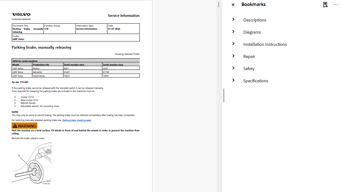
- Manual parking brake release
STEERING AND COMFORT DRIVE CONTROL
15. Hydraulic Steering System
The steering section covers the hydraulic components responsible for machine articulation.
Included components:
- Steering valve
- Steering cylinders
- Steering pressure monitor
- Secondary steering pump
- Secondary steering system
- Hydraulic steering valve block
Steering repair procedures:
- Steering working pressure checking
- Steering pressure adjustment
- Steering valve replacement
- Left steering cylinder removal and installation
- Right steering cylinder removal and installation
- Steering cylinder reconditioning
- Secondary steering pump pressure checking and adjustment
16. Comfort Drive Control (CDC)
The manual includes descriptions and repair instructions for the CDC lever steering system.
CDC servicing:
- CDC angle sensor replacement
- CDC control valve removal
- CDC control valve installation
- CDC solenoid valve replacement
- CDC servo pressure checking
- CDC lever steering functional checking
FRAME, CAB AND OPERATOR ENVIRONMENT
17. Frame and Wheels
The structural section includes:
- Frame joint bearing replacement
- Axle suspension bush and seal replacement
- Front wheel removal and installation
- Rear wheel removal and installation
- Frame and wheel tightening torque references
18. Cab and Air Conditioning
The cab section contains repair procedures for operator environment components.
Cab repairs:
- Cab removal and installation
- Engine hood removal and installation
- Door lock replacement
- Door lock cylinder replacement
- Side window replacement
- Windscreen replacement
- Viscous cab suspension replacement
- Operator seat securing
Air conditioning repairs:
- Compressor replacement
- Condenser replacement
- Evaporator replacement
- Expansion valve replacement
- Receiver replacement
- Heater core replacement
- Heat control valve replacement
- Fan motor replacement
- Air mix door actuator replacement
- Climate unit removal and installation
- Electronic Climate Control replacement
Several air conditioning procedures include refrigerant draining and refilling operations.
WORKING HYDRAULIC SYSTEM
19. Hydraulic System Components
The hydraulic chapters describe the machine's working hydraulic circuits.
Components and functions include:
- Hydraulic oil tank
- Hydraulic pumps
- Hydraulic pump flow regulation
- Central valve
- Control valve
- Servo valve
- Servo system
- Shift valve
- Hydraulic pressure monitor
- Hydraulic attachment bracket
- Floating position
- TP-Linkage bearing points
20. Hydraulic Pumps P2 and P3
The repair section includes procedures for hydraulic pumps P2 and P3.
Pump P2:
- Removal
- Installation
- Technical specifications
Pump P3:
- Removal
- Installation
- Fan control pressure checking
- Cooling fan speed adjustment
- Standby pressure adjustment
General hydraulic pressure procedures:
- Maximum working pressure checking
- Maximum working pressure adjustment
- Standby pressure checking
- Standby pressure adjustment
- Hydraulic system bleeding
21. Hydraulic Control and Servo Valves
The manual provides instructions for servicing hydraulic control components.
Included procedures:
- Central valve removal and installation
- Control valve removal and installation
- Servo valve removal and installation
- Servo valve control adjustment
- Servo accumulator removal and installation
- Servo pressure checking and adjustment
- Servo pressure measurement at the control valve spool
- Back-up valve checking and adjustment
- Back-up valve replacement
22. Lift and Tilt Cylinder Repairs
The manual includes procedures for servicing hydraulic cylinders directly on the machine.
Workshop operations:
- Lift cylinder repacking in the machine
- Tilt cylinder repacking in the machine
- Tilt function checking
- Lift function shock valve checking
- Tilt function shock valve checking
23. Third and Fourth Hydraulic Functions
The auxiliary hydraulic chapters address additional hydraulic equipment and attachment control.
Included information:
- Third hydraulic function
- Third and fourth hydraulic functions
- Auxiliary hydraulic valve descriptions
- Hydraulic control valve removal
- Hydraulic control valve installation
- Hydraulic valve section replacement
- Third and fourth hydraulic pressure checking and adjustment
- Attachment locking checking
- Attachment locking hydraulic cylinder
BOOM SUSPENSION AND LUBRICATION
24. Boom Suspension System (BSS)
The BSS documentation includes component descriptions and repair procedures.
Boom Suspension System servicing:
- Accumulator checking
- Accumulator pressure adjustment
- Accumulator reconditioning
- Left accumulator removal
- Left accumulator installation
- Hydraulic oil pressure procedures
- BSS test drive with load
25. Automatic Lubrication System
The manual contains information about the central lubrication equipment.
Included topics:
- Central lubrication system description
- Lubrication pump unit
- Dosage valves
- Lubrication interval adjustment
- Lubricant filling
- Automatic lubrication pump reconditioning
- Automatic lubrication system update
26. Fire Suppression System
The publication includes:
- Fire suppression system descriptions
- Fire suppression component information
- Actions following automatic activation
- Actions following manual activation
- Fire suppression system specifications
HYDRAULIC CIRCUIT DIAGRAMS
The manual contains complete hydraulic diagrams and explanations.
Included references:
- Complete hydraulic diagram
- Additional hydraulic diagram versions
- Hydraulic circuit explanations
These diagrams support the repair procedures for steering, working hydraulics, hydraulic control valves, and related components.
OPTIONAL EQUIPMENT INSTALLATION
The installation section includes instructions for selected accessories and machine configurations.
Hydraulic Equipment
- Third hydraulic function
- Third and fourth hydraulic functions
- Attachment locking
- Boom Suspension System
- Single-lever control for second hydraulic function
- Single-lever control with third hydraulic function
Engine and Cooling Equipment
- Engine heater 120V, 550W
- Extra fuel filter
- Reversible fan
- Corrosion-protected radiator
- Oil-bath air pre-cleaner
- Cab air pre-cleaner
- Hand throttle
Electrical and Cab Equipment
- CareTrack
- Comfort Drive Control
- Air conditioning kit
- Radio kit
- Electrically heated and adjustable rear-view mirrors
- Forward-view camera
- Rear-view camera
- Front-view mirror
Lighting and Protection
- Front work lights
- Rear work lights
- Attachment work light
- Rotating beacon
- Front lighting protection
- Radiator grille guard
- Tail lamp guard
- Mudflaps and splash plates
Optional equipment instructions must be matched to the machine's installed configuration.
WORKSHOP SAFETY INFORMATION
The manual includes safety guidance for servicing heavy construction equipment.
Safety topics:
- General service safety
- Hydraulic accumulator handling
- Hydraulic system safety
- Electrical system precautions
- Battery handling
- Air conditioning refrigerant safety
- Safe lifting and supporting
- Working under a raised boom
- Tyre handling
- Oil and fuel handling
- Fire prevention
- Inspection following fire or heat exposure
- Decontamination
- Environmental protection
- Hazardous fluid disposal
- Waste management
TECHNICAL SPECIFICATIONS
The manual provides reference data for the main machine systems.
| System | Technical Information |
|---|---|
| Engine | Specifications, capacities, valve system data |
| Fuel system | Fuel feed pump, fuel pressure references, tightening torques |
| Cooling | Cooling fan speed, thermostat, coolant capacity |
| Electrical | Alternator, battery, lighting, preheating, starter motor |
| Transmission | Hydraulic transmission specifications and capacities |
| Axles | Front and rear axle capacities and tightening torques |
| Brakes | Brake accumulators, wheel brakes, parking brake |
| Steering | CDC, secondary steering pump, steering specifications |
| Frame | Frame joint, wheel specifications |
| Cab | Air conditioning, refrigerant quantities, cab tightening torques |
| Hydraulics | Pump P2/P3, servo system, hydraulic oil volume |
| Auxiliary hydraulics | Third and fourth hydraulic functions |
| Boom suspension | BSS specifications and tightening torques |
| Lubrication | Automatic lubrication system specifications |
| Fire suppression | Fire suppression system specifications |
REPAIR TASKS SUPPORTED BY THIS MANUAL
This publication can be consulted when performing:
- Common Rail fuel system diagnostics
- High-pressure fuel pump replacement
- Fuel pressure sensor replacement
- Engine compression testing
- Turbocharger inspection
- Hydraulic cooling fan adjustments
- VCADS Pro diagnostic operations
- Electronic control module replacement
- SAE fault code investigation
- Electrical wiring troubleshooting
- Transmission pressure testing
- Hub reduction reconditioning
- Differential lock adjustment
- Brake accumulator testing
- Foot brake valve reconditioning
- CDC steering maintenance
- Hydraulic pump pressure adjustments
- Lift and tilt cylinder repacking
- Boom Suspension System maintenance
- Automatic lubrication servicing
- Air conditioning component replacement
WHO SHOULD USE THIS MANUAL?
The documentation is suitable for:
- Heavy equipment mechanics
- Volvo wheel loader service workshops
- Diesel engine repair specialists
- Hydraulic repair technicians
- Electrical diagnostics technicians
- Construction fleet maintenance departments
- Experienced Volvo L60F owners
VERIFY YOUR MACHINE BEFORE PURCHASE
This publication is identified for the Volvo L60F Wheel Loader.
Please confirm your machine model, serial number, engine configuration, electronic control system, and installed optional equipment before ordering.
Some procedures and diagrams may correspond to particular machine configurations.
Technical Information Updated: 2023 refers to the update year of the technical documentation and does not necessarily indicate the manufacturing year of the equipment.
DIGITAL PDF PRODUCT
You are purchasing a 1,905-page Volvo L60F service repair manual in PDF format.
The documentation includes repair instructions, component descriptions, electronic diagnostic references, wiring diagrams, hydraulic schematics, installation instructions, safety information, and specifications.
This is a digital product. No printed manual or physical item will be shipped.
A PDF reader is required to open the document.
IMPORTANT DOWNLOAD INFORMATION
Due to the large file size, this manual is delivered via a Dropbox download link to ensure a smooth downloading experience without overloading our website. No software installation, Dropbox account, or login is required to access and download your manual. Simply open the provided link and download the file directly to your device. If you experience any issues accessing or downloading your manual, please don't hesitate to contact us. We're always happy to help and will assist you as quickly as possible!
EXPLORE MORE VOLVO SERVICE MANUALS
BROWSE VOLVO WHEEL LOADER MANUALS
More products


