$14.60
VOLVO L90D WHEEL LOADER SERVICE REPAIR MANUAL PDF – 863 PAGES
Volvo L90D Workshop Manual – Engine Repair, Fuel Injection Timing, APS II, HT131 Transmission, Brakes, Steering and Hydraulics
Repairing a Volvo L90D wheel loader requires more than basic maintenance instructions. Accurate pressure checks, correct component adjustments, electrical circuit information, and mechanical repair procedures are essential when servicing the machine's engine, transmission, brakes, steering, and hydraulic equipment.
The Volvo L90D Wheel Loader Service Repair Manual provides 863 pages of workshop documentation, bringing together technical descriptions, component servicing procedures, electrical wiring diagrams, hydraulic schematics, installation instructions, and machine specifications.
The publication covers the mechanical engine assemblies, fuel injection pump, injector components, cooling system, electronic control functions, hydraulic transmission, drive axles, wheel brakes, steering equipment, and working hydraulic circuits.
Among its most useful sections are the procedures for checking and setting fuel injection timing, adjusting engine idle speed, testing fuel feed pump pressure, inspecting transmission clutch pressures, servicing brake components, and adjusting hydraulic working pressure.
The electrical chapters address APS II, Vehicle Control Unit (V-ECU), Instrument Control Unit (I-ECU), electronic communication, machine monitoring, and numbered wiring diagrams.
The hydraulic chapters include information about Boom Suspension System BSS400, servo pressure, shock valves, hydraulic lifting and tilting functions, and hydraulic circuit diagrams.
This manual is intended for experienced machinery technicians, independent repair workshops, construction equipment maintenance personnel, and Volvo L90D owners who require detailed workshop references.
MANUAL INFORMATION
- Manufacturer: Volvo Construction Equipment
- Equipment Model: Volvo L90D Wheel Loader
- Manual Type: Service Repair / Workshop Manual
- Format: PDF
- Total Pages: 863
- Language: English
- Technical Information Updated: 2022
- Delivery: Digital Download
A CLOSER LOOK AT THE SERVICE DOCUMENTATION
The manual is arranged around the machine's main service groups, including general maintenance, engine, electrical system, transmission, brakes, steering, frame, cab, and working hydraulics.
It also contains installation instructions for selected accessories and optional equipment.
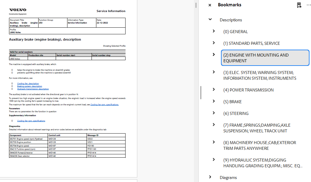
1. GENERAL WORKSHOP INFORMATION
The opening section provides the reference information needed before performing mechanical or hydraulic repairs.
Included subjects:
- General service information
- Machine product identification plates
- Fluid capacities
- Conversion tables
- Standard tightening torques
- Component tightening torques
- Machine weights
- Workshop time guide
- Machine transportation
- Transporting a wheel loader on another vehicle
- Recommended lubricants
- Coolant recommendations
2. ROUTINE SERVICE AND MAINTENANCE
The service section addresses inspection and maintenance operations on the principal machine systems.
Maintenance procedures include:
- Engine oil replacement
- Engine oil filter replacement
- Engine air cleaner servicing
- Air cleaner filter indicator checking
- Secondary safety filter servicing
- Oil-bath pre-cleaner servicing
- Axle oil changing
- Transmission servicing
- Fuel system maintenance
- Battery charging
- Hydraulic system maintenance
- Brake and hydraulic system cleanliness
- Electrical welding precautions
- Propeller shaft removal
- Manual parking brake release
- Towing procedures
- Starting with booster batteries
3. ENGINE CONSTRUCTION AND INTERNAL COMPONENTS
The engine chapters include descriptions of the principal internal engine assemblies.
Mechanical engine components:
- Cylinder block
- Cylinder head
- Cylinder liners
- Crankshaft
- Camshaft
- Connecting rods
- Pistons and piston rings
- Main and connecting rod bearings
- Flywheel
- Vibration damper
- Engine transmission components
The manual also includes engine removal and installation procedures.
4. TD63 AND TD73 FUEL SYSTEM INFORMATION
The engine documentation contains references to TD63 and TD73 fuel injection systems, including model-specific technical information.
Fuel injection subjects:
- Fuel injection pump, TD63
- Fuel injection pump, TD73
- Fuel feed pump
- Injector copper tubes
- Fuel system bleeding
- Fuel feed pressure testing
- Injection timing
- Engine idle adjustment
- Engine stop solenoid
Repair and adjustment procedures:
- Fuel feed pump pressure checking
- Fuel injection timing checking
- Fuel injection timing setting
- Injector copper tube replacement
- Fuel system bleeding
- Stop solenoid stroke adjustment
- Stop solenoid troubleshooting
Because the publication includes some shared L90D/L120D references, technicians should verify the applicable engine and machine configuration before using model-specific specifications.
5. ENGINE ADJUSTMENTS AND PERFORMANCE CHECKS
The manual includes procedures for verifying engine operating conditions.
Included operations:
- Engine stall speed checking
- Engine idle speed checking
- Engine idle speed adjustment
- Engine valve adjustment
- Injection timing adjustment
- Fuel feed pressure checking
- Stop solenoid adjustment
These procedures support workshop diagnosis and engine performance checks.
6. ENGINE LUBRICATION SYSTEM
The lubrication section describes the circulation and servicing of engine oil.
Included information:
- Engine lubrication system
- Lubrication system for TD63
- Oil cooler
- Engine oil changing
- Engine oil filter changing
- Lubrication system specifications
- Engine fluid capacities
7. COOLING SYSTEM AND HYDRAULIC FAN
The manual includes descriptions and servicing procedures for the cooling system.
Cooling system topics:
- Radiator
- Engine coolant pump
- Intercooler coolant pump
- Hydraulically driven cooling fan
- Cooling fan hydraulic diagram
- Engine cooling components
Workshop procedures:
- Radiator removal
- Radiator installation
- Engine coolant pump removal
- Engine coolant pump installation
- Intercooler coolant pump servicing
- Intercooler coolant pump reconditioning
8. ELECTRONIC CONTROL SYSTEM
The electrical section explains the machine's electronically monitored functions.
Control systems include:
- Vehicle Control Unit (V-ECU)
- Instrument Control Unit (I-ECU)
- Electronic control system
- Software functions
- Data bus communication
- Machine electrical system
Software function categories:
- Engine
- Electrical system
- Power transmission
- Brakes
- Steering
- Hydraulics
9. APS II AND TRANSMISSION CONTROL
The manual contains references to APS II and electronically controlled transmission functions.
Documented functions include:
- APS II
- Gear selector
- Gear shifting solenoids
- Downshift audible signal
- Transmission disengagement
- Transmission overspeed monitoring
- Transmission oil pressure
- Transmission oil temperature
- Transmission oil filter monitoring
10. MACHINE INFORMATION DISPLAY
The Volvo L90D service documentation includes information about the operator display and its diagnostic functions.
Display sections:
- Initial display
- Operating display
- Information display
- Display settings
- Service display
- Engine information
- Transmission information
- Axles and brakes
- Hydraulic system
- Electrical system battery voltage
- Electrical control input signals
- Electrical control output signals
- Service intervals
The manual also addresses communication interruptions, reduced communication, and limp-home operation.
11. ELECTRICAL COMPONENTS AND WARNING SYSTEMS
The electrical chapters provide descriptions and specifications for machine electrical components.
Included subjects:
- Alternator
- Battery
- Starter motor
- Starter inhibitor
- Starter motor engagement
- Electrical distribution box
- Lighting
- Back-up alarm
- Central warning functions
- Engine shutdown
- Engine power reduction
- Engine preheating
- Cooling fan control
- Differential lock monitoring
- Parking brake monitoring
- Secondary steering monitoring
- Hydraulic oil temperature monitoring
- Coolant temperature monitoring
12. ELECTRICAL WIRING DIAGRAMS
The manual contains a numbered collection of wiring diagrams for tracing electrical circuits and machine control signals.
Included diagram references:
- Wiring diagrams 1–26
- Wiring diagram 21C
- Wiring diagram 32
- Wiring diagram 32B
- Wiring diagram 140
- Wiring diagram 190
The table of contents also identifies Wiring Diagram 10 – Transmission Sensors.
Additional electrical documentation includes component designations, circuit lists, electrical symbols, communication cables, and chassis connections.
13. HT131 HYDRAULIC TRANSMISSION
The power transmission section includes specific references to the HT131 transmission for the L90D.
Transmission information:
- Hydraulic transmission description
- HT131 symbol diagram
- Hydraulic transmission oil pressure checking
- Transmission clutch pressure chart
- Gear selector valve
- Transmission neutral position information
- Limp-home operation
- Transmission troubleshooting
Mechanical repair procedures:
- Transmission removal
- Transmission installation
- Differential lock adjustment
- Front axle removal
- Front axle installation
- Rear axle removal
- Rear axle installation
14. DRIVE AXLES AND DIFFERENTIAL LOCK
The manual includes servicing information for the machine's drive axles.
Included topics:
- Front axle
- Rear axle
- Differential lock adjustment
- Axle removal and installation
- Axle oil replacement
- Propeller shaft removal
- Axle capacities
- Axle weights
- Tightening torque specifications
15. SERVICE BRAKE SYSTEM
The brake section includes hydraulic diagrams, pressure checks, component servicing, and brake performance testing.
Brake system procedures:
- Brake system bleeding
- Brake circuit pressure checking
- Brake circuit pressure adjustment
- Brake retardation functional checking
- Brake disc wear inspection
- Brake disc replacement
- Removed brake accumulator checking
- Foot brake pedal angle adjustment
- Foot brake pedal clearance adjustment
- Foot brake valve reconditioning
16. PARKING BRAKE SYSTEM
The publication includes information for different parking brake arrangements.
Parking brake topics:
- Mechanical parking brake operation
- Hydraulically controlled parking brake
- Manual parking brake release
- Parking brake checking
- Parking brake adjustment
- Parking brake pad servicing
The manual distinguishes between certain parking brake versions, so the correct procedure must be selected for the actual machine.
17. HYDRAULIC STEERING SYSTEM
The steering section describes the machine's steering components and operating principles.
Included components:
- Steering pump
- Steering valve
- Steering cylinders
- Hydraulic steering system
- Steering shift valve
- Secondary steering equipment
Workshop procedures:
- Steering standby pressure checking
- Steering working pressure checking
- Steering valve reconditioning
- Shift valve reconditioning
- Steering system hydraulic testing
18. COMFORT DRIVE CONTROL (CDC)
The manual contains references to CDC lever steering and its hydraulic circuits.
CDC-related subjects:
- CDC hydraulic steering diagrams
- Lever steering operation
- Lever steering speed adjustment
- Steering control valve checking
- Steering control valve adjustment
- CDC and secondary steering circuit arrangements
19. STEERING HYDRAULIC DIAGRAMS
The steering documentation includes several circuit configurations.
Diagram subjects:
- Standard hydraulic steering
- Steering with CDC
- Steering with secondary steering
- Steering with CDC and secondary steering
- Steering control valve arrangements
20. FRAME AND MACHINE STRUCTURE
The frame section contains structural descriptions and reference data.
Included information:
- Frame description
- Structural component weights
- General frame specifications
- Tightening torques
21. CAB AND OPERATOR ENVIRONMENT
The manual provides descriptions and service instructions for the cab and its supporting systems.
Cab components:
- Operator cab
- Cab suspension
- Heating system
- Ventilation system
- Air conditioning system
- Cab electrical system
Cab servicing procedures:
- Cab removal
- Cab installation
- Air conditioning performance checking
- Evaporator cleaning
22. WORKING HYDRAULIC SYSTEM
The hydraulic section explains the machine's working hydraulic circuits and related controls.
Hydraulic components:
- Working hydraulic system
- Hydraulic control valve
- Hydraulic lift cylinder
- Hydraulic tilt cylinder
- Hydraulic servo valve
- Hydraulic pressure regulation
- Shock and anti-cavitation valves
Hydraulic service procedures:
- Hydraulic system bleeding
- Hydraulic working pressure checking
- Hydraulic working pressure adjustment
- Servo pressure checking
- Servo pressure adjustment
- Servo pressure checking at control valve spool
- Servo control adjustment
23. HYDRAULIC SHOCK VALVES
The publication includes procedures for checking and adjusting hydraulic protection valves.
Included operations:
- Lift function shock valve checking
- Lift function shock valve adjustment
- Tilt function shock valve checking
- Tilt function shock valve adjustment
- Shock and anti-cavitation valve information
- Back-up valve opening pressure checking
24. BOOM SUSPENSION SYSTEM BSS400
The manual includes specific documentation for Boom Suspension System BSS400.
BSS400 information:
- BSS400 system description
- BSS400 electrical system description
- BSS400 hydraulic system description
- BSS400 functional checking
- Accumulator precharge pressure
- Servo circuit pressure support
- Pressure reducing valve references
25. HYDRAULIC CIRCUIT DIAGRAMS
The hydraulic section contains several diagrams.
Included diagrams:
- Complete L90D hydraulic diagram
- Working hydraulic system diagrams
- Steering hydraulic diagrams
- Brake hydraulic diagrams
- Hydraulically driven cooling fan diagram
Some diagram references are also provided for the L120D. These should not be substituted for L90D-specific diagrams without confirming applicability.
26. OPTIONAL EQUIPMENT INSTALLATION
The manual includes installation instructions for selected accessories and additional equipment.
Included installation subjects:
- Third hydraulic function
- Attachment locking
- Single-lever control
- Air conditioning
- Engine heater
- 120V engine heater
- Alternator/generator
- Electrically heated rear-view mirrors
- Radio installation kit
- Rotating warning beacon
- Rear working lights
- Headlamp protective grille
- Tail lamp guard
- Sun blind
- Instructor seat
- CareTrack
27. TECHNICAL SPECIFICATIONS AND REFERENCE TABLES
The publication includes technical specifications across the main machine systems.
| System | Available Reference Information |
|---|---|
| General | Capacities, weights, conversion tables, tightening torques |
| Engine | Engine specifications, fuel system data, mechanical assemblies |
| Fuel injection | Injection pump, feed pressure, timing references |
| Cooling | Coolant system and hydraulic fan information |
| Electrical | Alternator, batteries, starter motor, lighting |
| Transmission | HT131 transmission, clutch pressures, oil capacities |
| Drive axles | Front and rear axle specifications |
| Brakes | Hydraulic brake circuits, pressure settings, wear checks |
| Steering | Steering pressure and CDC hydraulic circuits |
| Frame | Structural specifications and weights |
| Cab | Air conditioning specifications and tightening torques |
| Hydraulics | Hydraulic working pressure, servo system, control valves |
| Boom suspension | BSS400 pressure and operating references |
WORKSHOP APPLICATIONS
This manual can be used as a reference for tasks such as:
- Checking engine fuel feed pressure
- Adjusting injection timing
- Adjusting engine idle speed
- Replacing injector copper tubes
- Removing and installing the engine
- Servicing the cooling system
- Checking electrical control functions
- Reading machine service display information
- Tracing electrical circuits
- Checking HT131 transmission pressure
- Investigating transmission shifting problems
- Removing and installing drive axles
- Inspecting brake disc wear
- Adjusting brake circuit pressure
- Reconditioning the foot brake valve
- Servicing the parking brake
- Checking hydraulic steering pressure
- Adjusting CDC lever steering
- Checking hydraulic servo pressure
- Adjusting hydraulic shock valves
- Testing BSS400 operation
- Servicing cab air conditioning
- Installing selected optional equipment
IMPORTANT MODEL COMPATIBILITY INFORMATION
This product is listed as the Volvo L90D Wheel Loader Service Repair Manual.
The publication's table of contents also contains certain technical references for the Volvo L120D, including shared descriptions, specifications, and diagrams.
These references do not mean that the entire manual is applicable to every L120D configuration.
Before purchasing, verify the exact model, serial number, engine version, transmission arrangement, and installed equipment.
Technical Information Updated: 2022 identifies the documentation update year, not necessarily the manufacturing year of the wheel loader.
DIGITAL MANUAL FORMAT
This product is supplied as an 863-page digital PDF service repair manual.
It contains workshop repair instructions, component descriptions, electrical wiring diagrams, hydraulic diagrams, installation information, and technical specifications.
Digital product only. No printed book or physical manual will be shipped.
A compatible PDF reader is required to open the document.
IMPORTANT DOWNLOAD INFORMATION
Due to the large file size, this manual is delivered via a Dropbox download link to ensure a smooth downloading experience without overloading our website. No software installation, Dropbox account, or login is required to access and download your manual. Simply open the provided link and download the file directly to your device. If you experience any issues accessing or downloading your manual, please don't hesitate to contact us. We're always happy to help and will assist you as quickly as possible!
EXPLORE OTHER VOLVO EQUIPMENT MANUALS
BROWSE VOLVO WHEEL LOADER MANUALS
VIEW ALL VOLVO EQUIPMENT MANUALS
EXPLORE THE COMPLETE MANUAL COLLECTION
Detailed contents:
Repair
(0) GENERAL
Capacities (2)
Capacities
Conversion tables
General
Product identification plates
Section 2 Engine (2)
Section 2 Engine
Section 3 Electrical system (2)
Section 3 Electrical system
Section 4 Power transmission (2)
Section 4 Power transmission (3)
Section 4 Power transmission
Section 5 Brakes (2)
Section 5 Brakes (3)
Section 5 Brakes
Section 6 Steering system (2)
Section 6 Steering system
Section 8 Cab (2)
Section 8 Cab
Section 9 Hydraulic system (2)
Section 9 Hydraulic system
Tightening torques (2)
Tightening torques
Time Guide
Transporting the machine
Volvo standard tightening torques
Weight (2)
Weight
(1) STANDARD PARTS, SERVICE
Axles, oil change
Charging of batteries
Cleanliness, brake and hydraulic systems
Coolant
Electric welding
Engine oil filter, changing
Engine oil, changing
Engine, air cleaner
Filter indicator, checking
Fuel system
Hydraulic system, general
Manual release of parking brake, L90D (2)
Manual release of parking brake, L90D
Manual release of parking brake, L120D
Oil-bath precleaner
Recommended lubricants
Removing propeller shafts
Repairing the hydraulic system
Safety filter (secondary filter)
Starting with booster batteries
Towing
Transmission
Transporting wheel loader on another vehicle
Washer fluid reservoir, windscreen rear window
(2) ENGINE WITH MOUNTING AND EQUIPMENT
Air cleaner, description
Checking stall speed
Combined tank unit, removing and installing
Coolant pump for Intercooler, reconditioning
Coolant pump for Intercooler,
Coolant pump, removing and installing
Copper tubes for injectors, changing
Description (2)
Description (3)
Description, camshaft
Description, connecting rods
Description, crankshaft
Description, cylinder block
Description, cylinder head
Description, cylinder liner
Description, engine transmission
Description, flywheel
Description, frame and big-end bearing
Description, general
Description, lubrication and oil system
Description, pistons and piston rings, L90D
Description, pistons, L120D
Description, vibration damper
Description
Descriptions
Engine, installing
Engine, removing
Fuel feed pump, checking feed pressure, L90D
Fuel feed pump, checking feed pressure
Fuel injection pump, TD63
Fuel injection pump, TD73
Fuel injection pump
Fuel system, bleeding
Hydraulic diagram, cooling fan (hydraulically driven)
Hydraulically driven cooling fan L120D, description
Hydraulically driven cooling fan, (2)
Hydraulically driven cooling fan,
Idle speed, checking and adjusting
Injection timing, checking and setting
Lubrication system, TD63
Oil cooler, description
Radiator, removing and installing
Specifications, air cleaner
Specifications, capacities (2)
Specifications, capacities (3)
Specifications, capacities (4)
Specifications, capacities, L90D
Specifications, capacities, L120D
Specifications, capacities
Specifications, general (2)
Specifications, general (3)
Specifications, general, L90D and L120D
Specifications, general, L90D L120D (2)
Specifications, general, L90D L120D
Specifications, general, L90D
Specifications, general, L120D
Specifications, general
Specifications, L90D
Specifications, L120D
Specifications, tightening torques (2)
Specifications, tightening torques
Specifications, weight (2)
Specifications, weight
Specifications
Stop solenoid, adjusting stroke
Stop solenoid, description
Stop solenoid, troubleshooting advice
Valves, adjusting
(3) ELEC. SYSTEM; WARNING SYSTEM; INFORMATION SYSTEM; INSTRUMENTS
2 Software functions, engine
3 Software functions, electrical system
4 Software functions, power transmission
5 Software functions, brakes
6 Software functions, steering system
9 Software functions, hydraulic system
Alternator, description
Alternator, specifications
APS II
Axle oil temperature
Back-up alarm
Battery, charging
Battery, description
Battery, specifications
Boom Suspension System (BSS)
Brake pressure
Brake test
Break in computer communication
Central lubrication
Chassis connections
Circuit list
Communication with data buses
Control units, software functions
Coolant temperature, engine
Coolant temperature, outlet, radiator
Description of software functions table
Differential lock
Display panel and keypad, general
Display panel, general
Display panel, information displays
Display panel, initial display
Display panel, operating display
Display panel, setting
Downshift audible signal (beep)
Electrical components
Electrical distribution box, description
Electrical symbols and designations
Electrical system, description
Electrical system, instructions for working on the electrical system
Electrical system, specifications
Electronic control system, description
Engine oil pressure
Engine Shut Down (power reduction)
Engine Shutdown
Engine speed for V-ECU
Explanations of cable and component markings
Fuel level
Gear selector
Gearshifting solenoids
Hydraulic oil temperature
Instrument control unit I-ECU, functional description
Instruments
Interval wiper
ir filter pressure
Key to communication cables
Lighting, description
Lighting, specifications
Limp-Home, by-passed V-ECU
Middle instrument panel with warning lamps
Output brake pressure
Overspeed transmission
Parking brake, electric
Parking brake, mechanical (L90D)
Positive feed
Preheating of induction air
Preheating, description
Radiator fan control
Reduced computer communication
Secondary steering
Service display unit, axles and brakes
Service display unit, electrical control input signals 1
Service display unit, electrical control input signals 2
Service display unit, electrical control input signals 3
Service display unit, electrical control output signals 1
Service display unit, electrical control output signals 2
Service display unit, electrical system battery voltage (2)
Service display unit, electrical system battery voltage
Service display unit, engine
Service display unit, general
Service display unit, hydraulics
Service display unit, settings
Service display unit, transmission
Service interval
Signal earth
Starter inhibitor
Starter motor engagement
Starter motor, specifications
Starting system, description
System voltage
Transmission disengagement
Transmission oil filter
Transmission oil pressure
Transmission oil temperature
Travel speed
Tyre radius
Vehicle control unit V-ECU, functional description
Wiping during and after washing
Wiring diagram 1
Wiring diagram 2
Wiring diagram 3
Wiring diagram 4
Wiring diagram 5
Wiring diagram 6
Wiring diagram 7
Wiring diagram 8
Wiring diagram 9
Wiring diagram 10. Sensors transmission
Wiring diagram 11
Wiring diagram 12.
Wiring diagram 13.
Wiring diagram 14
Wiring diagram 15.
Wiring diagram 16.
Wiring diagram 17.
Wiring diagram 18.
Wiring diagram 19.
Wiring diagram 20.
Wiring diagram 21.
Wiring diagram 21C.
Wiring diagram 22.
Wiring diagram 23.
Wiring diagram 24.
Wiring diagram 25.
Wiring diagram 26.
Wiring diagram 32.
Wiring diagram 32B.
Wiring diagram 140.
Wiring diagram 190.
(4) POWER TRANSMISSION
Clutch pressure chart, L90D∗
Clutch pressure chart, L120D∗
Description 2
Description
Differential lock, adjusting
Front axle, installing
Front axle, removing
Gear selector valve, description
Hydraulic transmission, checking oil pressure
Hydraulic transmission, description
Limp-home operation
Neutral position, HT205
Rear axle, installing
Rear axle, removing
Specifications, capacities 2
Specifications, capacities 3
Specifications, capacities 4
Specifications, capacities
Specifications, general 2
Specifications, general
Specifications, L90D 2
Specifications, L90D and L120D, general
Specifications, L90D, capacities
Specifications, L90D, general 2
Specifications, L90D, general
Specifications, L90D, weight 2
Specifications, L90D, weight 23
Specifications, L90D, weight
Specifications, L90D
Specifications, L120D 2
Specifications, L120D, capacities
Specifications, L120D, general 2
Specifications, L120D, general
Specifications, L120D, weight
Specifications, L120D
Specifications, tightening torques 2
Specifications, tightening torques
Specifications, weight 2
Specifications, weight 3
Specifications, weight 4
Specifications, weight
Symbol diagram, HT131, L90D
Symbol diagram, HT205, L120D
Transmission, installing
Transmission, removing
Troubleshooting tips
(5) BRAKE
Accumulator, checking (removed)
Brake discs, changing
Brake discs, checking wear
Brake system, bleeding
Brake system, retardation, checking function
Checking function
Description 2
Description 3
Description
Discarded accumulators
Foot brake pedal, adjusting angle and pedal clearance
Foot brake valve (removed), reconditioning
Function
Hydraulic diagram, brakes, L90D
Hydraulic diagram, brakes, L120D
Parking brake (hydraulic), brake pad
Parking brake (hydraulically controlled), checking and adjustment, later version
Parking brake (mechanically operated),
Pressure in circuit, checking and adjusting
Specifications, general 2
Specifications, general 3
Specifications, general 4
Specifications, general
Specifications, L90D, general
Specifications, L120D, general
Wear indicator, description
(6) STEERING
Description 3
Description 4
Description 23
Description, general
Description
Function
Hold (stand-by) pressure and working pressure,
Hydraulic diagram, steering, from and
Hydraulic diagram, steering, incl. lever steering (CDC) 2
Hydraulic diagram, steering, incl. lever steering (CDC) 3
Hydraulic diagram, steering, incl. lever steering (CDC) and secondary steering
Hydraulic diagram, steering, incl. lever steering (CDC)
Hydraulic diagram, steering, incl. secondary steering 2
Hydraulic diagram, steering, incl. secondary steering
Hydraulic diagram, steering,
Hydraulic system, description
Lever steering, adjusting steering speed
Lever steering, checking and adjusting control valve
Shift valve L120D, description
Shift valve, reconditioning (removed)
Specification L90D, general 2
Specification L90D, general
Specification L120D, general 2
Specification L120D, general
Steering cylinder, description
Steering pump, description
Steering valve, description
Steering valve, reconditioning (removed)
Wiring diagrams 17 and 9
(7) FRAME; SPRINGS; DAMPING; AXLE SUSPENSION; WHEEL, TRACK UNI
Description
L90D specifications, weight 2
L90D specifications, weight 3
L90D specifications, weight
L120D specifications, weight 2
L120D specifications, weight 3
L120D specifications, weight
Specifications, tightening torques
Specifications, weight
(8) MACHINERY HOUSE; CAB; EXTERIOR TRIM PARTS ANYWHERE
AC safety, description
Air conditioning, checking performance
Air-conditioning unit, specifications
Cab suspension, description
Cab, installing
Cab, removing
Components
Electrical system, description
Evaporator in the air-conditioning unit, cleaning
Heating, ventilation and air conditioning unit, description 2
Heating, ventilation and air conditioning unit, description
Tightening torques
Weights 2
Weights
(9) HYDRAULIC SYSTEM, DIGGING, HANDLING, GRADING EQUIPM, MISC. EQUIP
Back-up valve, opening pressure, checking
Boom Suspension System (BSS400), checking function
Boom Suspension System (BSS400), electrical system description
Boom Suspension System (BSS400), hydraulic system description
Boom Suspension System (BSS400)
Control valve
Description
Hydraulic diagram L90D, complete
Hydraulic diagram L120D, complete
Hydraulic diagram, working hydraulic system 2
Hydraulic diagram, working hydraulic system 3
Hydraulic diagram, working hydraulic system
Hydraulic system, bleeding
L90D specifications, weight 2
L90D specifications, weight
L120D specifications, weight 2
L120D specifications, weight
Lift cylinder
Precharge pressure in accumulators,
Pressure back-up for servo circuit,
Pressure reducing valve (CT8) for
Servo pressure, checking and adjusting 2
Servo pressure, checking and adjusting
Servo pressure, checking by spool in control valve
Servo valve, functional description
Servo valve, operating controls, adjusting
Shock and anti-cavitation valve
Shock valve, lift function, checking and adjusting
Shock valve, tilt function, checking and adjusting
Specification L90D, general 2
Specification L90D, general 3
Specification L90D, general 4
Specification L90D, general 5
Specification L90D, general
Specification L120D, general 2
Specification L120D, general 3
Specification L120D, general 4
Specification L120D, general 5
Specification L120D, general
Specifications, general 2
Specifications, general
Specifications, L90D, capacities 2
Specifications, L90D, capacities
Specifications, L120D, capacities 32
Specifications, L120D, capacities
Specifications, tightening torques 2
Specifications, tightening torques
Specifications, weight 2
Specifications, weight
Tilt cylinder
Working hydraulic system, description
Working pressure, checking and adjusting
Installation Instructions
Installation
Working light, rear 2
Working light, rear
Sun blind
Rotating warning beacon
Electrically heated rear-view mirrors
Radio installation kit
Protective grille, headlamp
Tail lamp guard
Single lever control
3rd hydraulic function 2
Seat for the instructor
Installlation kit for Air
Engine heater, 120 V (USA)
Electrical engine heater
care track
Attachment lock
Alternator Generator
Air conditioning
3rd hydraulic function
More products


